Meshtastic is a mesh networking protocol that uses LoRa technology. It is specifically designed for hikers, backpackers, cyclists, and other outdoor enthusiasts who want to stay connected without a cellular network. Meshtastic devices form an ad-hoc mesh network, where each device acts as both a transmitter and receiver, enabling communication over a wide area without a centralized infrastructure.
Meshtastic devices use LoRa technology, which enables long-range communication with low power consumption. This makes them ideal for camping and hiking where cellular coverage may not be available. Meshtastic devices can send text messages, GPS locations, and other information between devices on the network.
Meshtastic devices can be configured and managed using a mobile app or a computer program. Users can create their own networks, assign device roles, and send messages between devices on the network. Meshtastic is an open source project, and the community is constantly developing new features and improvements.
I have installed Meshtastic both with the online tool and also with VS Code and Platform IO.
Compiling and uploading Meshtastic code to a device using Platform IO
The final version seems to be this:
https://github.com/meshtastic/firmware/releases/tag/v2.7.15.567b8ea
The following method is based on the fact that I have git and platform-io installed.
Windows Power Shell:
So you need to change to whatever directory you want to create the project in. The directory name must not contain spaces.
cd c:\temp\platformio\
Then you need to clone it from github, where the Meshtastic code is. The address is:
git clone https://github.com/meshtastic/firmware.git
cd firmware
git submodule update --init
git pull --recurse-submodules
then I open VS Code,
I open the folder.
c:\temp\platformio\firmware
Then you need to open that project in Platform IO, and then just compile and download it to the device.
and I wait until platform IO has recognized the device and then I just compile and load it onto the device.
I don't know why I had to put git add . even though I didn't change anything, but it doesn't let me change the branch. So:
git add .
Then:
git commit -m "no changes"
I read on the website that the stable version number is as follows:
stable version
v2.7.15.567b8ea
So after that:
git checkout v2.7.15.567b8ea
And then I just compile and upload it to the device.
it works with Platform IO and the check and -> symbols at the bottom of the VS Code window
Compiling and downloading Meshtastic code to your device using an online tool
https://flasher.meshtastic.org/

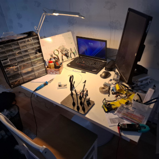
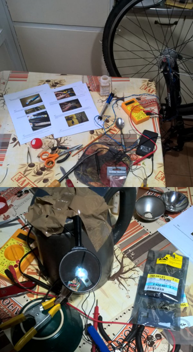
I took a photo of my hobby table: on the right there is a small drawer with numerous components: transistors, Arduinos, sensors, LEDs, potentiometers, pushbuttons, wires, chips, amplifiers, capacitors, and other small stuff. Behind it is a nail table with scissors, various pliers, magnifying glasses, and tweezers hanging so that they are always in order. On the right side of the table is also a soldering iron and the related materials in a tin box: soldering fluid, tip cleaning sponge, and soldering tin. In front is a magnetic table with holders that hold the components to be soldered in place because sometimes I do soldering. On the left is a multimeter and various wires, tape, and more tools. I think good lighting is also important.
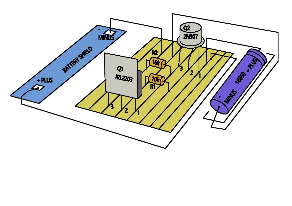
Since I put the 18650 battery in the reverse side of the charger unit twice, I started thinking about how to prevent this. I found a tutorial on the web, where a development is presented, with step by step improvements. The address is:
From this I have only picked out the last protection circuit:
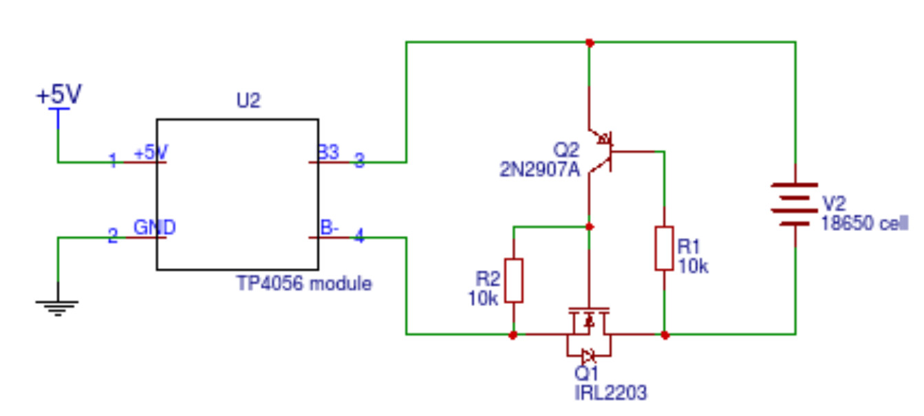
I made myself an isometric picture of this, because I have no idea about the placement of the MOSFET transistor pins.
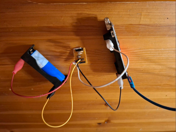
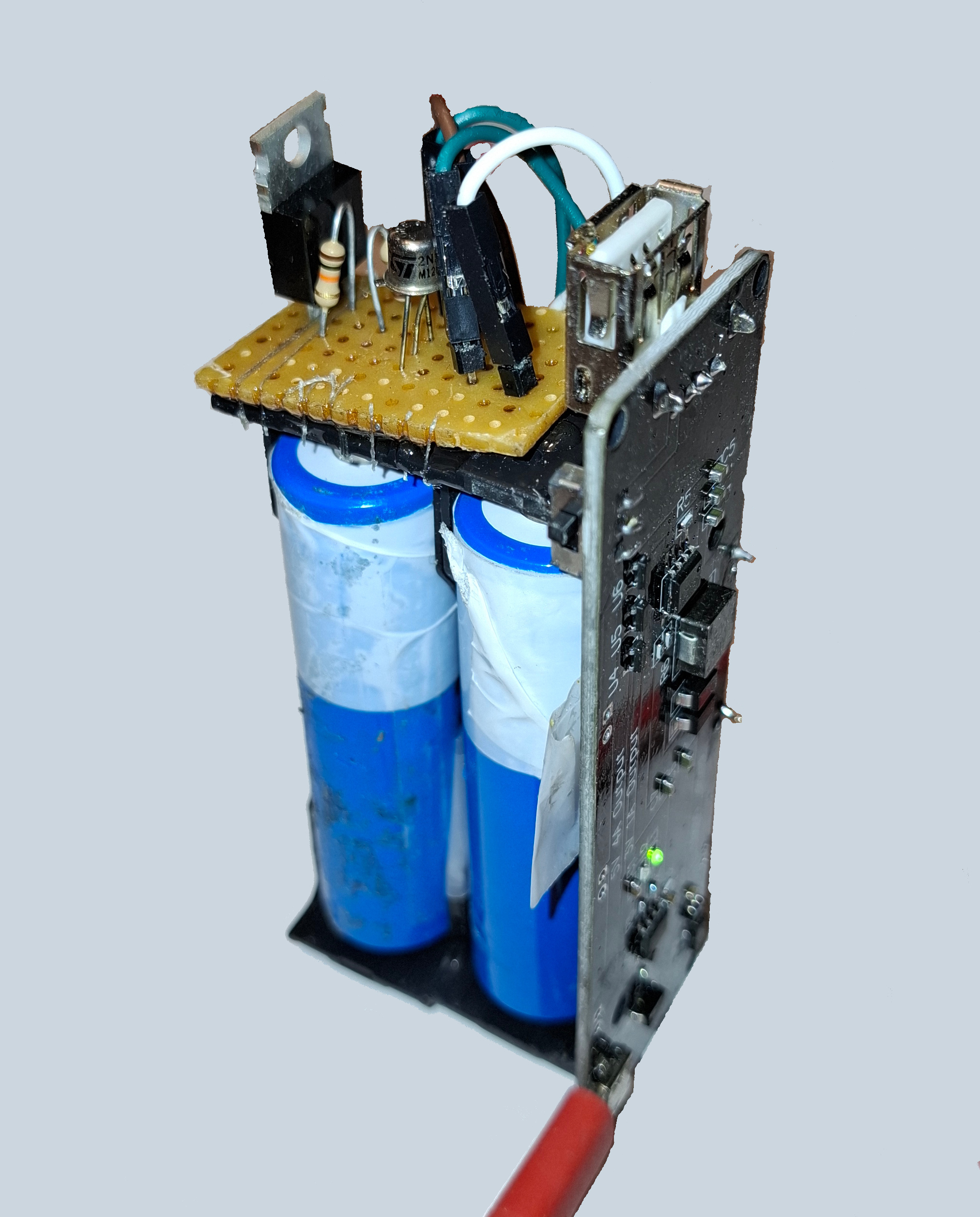
Here is a photo of the circuit, you can see what kind of leads I have used and how I have soldered the components to the board.
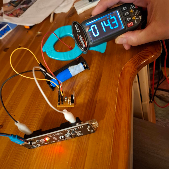
Another photo of the same circuit. I did indeed connect the 18650 correctly first. No fume rose from that. I was quite relieved. I had to gather all my courage before I put the 18650 battery in the wrong way round. Now I have a new multimeter, which also has a current measurement feature. The right way up the charging current was about 14.3 mA, the wrong way up there was no current at all. So it works now. I soldered another copy of this wiring tonight, so if I have two compass belts, I could protect both from inserting the battery the wrong way into the case!
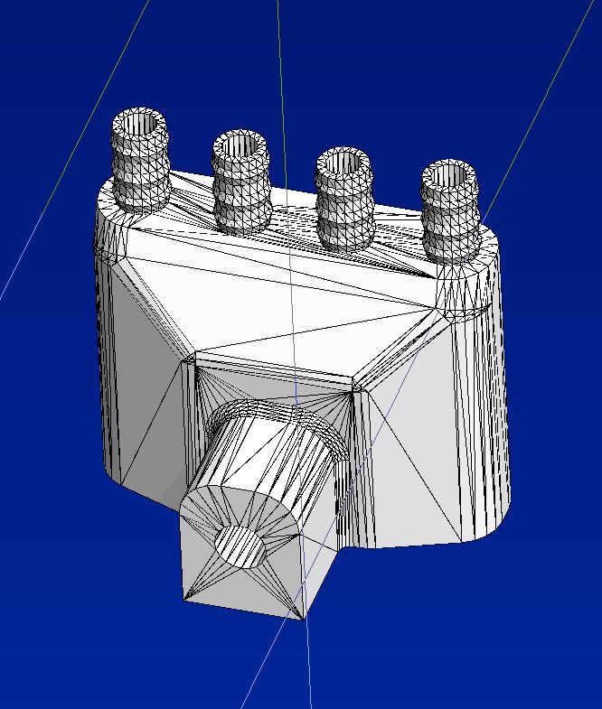
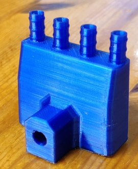
In connection with the flower watering arduino experiments, I wanted the same amount of water to always go to the four flower pots. I imagined it would be easy to do, but it's not. For some reason, the water always goes to one flower pot too much, and the other flower pot has nothing. I imagined that if I made holes of the same size, it would work. First, I made a trial version out of plastic blocks by gluing, and by poking with a needle I made holes of the same size as possible, a bit similar idea to hospital infusion drip devices. It didn't work, always a hole was a little bigger and then the water only went to one pot. That's why I decided that if I tried 3D printing, the holes should be precise. It still didn't work. What it looked like on the inside looked like half.
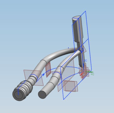
That's what the stl model looked like from the outside. I saved the "stl" file of that 3d model to the Cloud server, because the file was too big, I could not sent it as an email attachment. When I drew the model with the Unigraphics program, nowadays the name of the program is "Siemens NX", it was also a nice exercise in 3d modeling for me. For example, I had to remember that a 3d printer cannot have arbitrary protrusions, because it always prints a layer of plastic on top of another layer, and when that plastic is a bit hot, it might clump up a bit and lose its shape. Siemens NX is very suitable for modeling special wavy and curved surfaces.
I found the printing service on the www.tori.fi website. www.tori.fi is mainly an online sale of used goods, similar to what the yellow pages used to be. The 3-d model cost me about 15 Euro, and it came by mail quite quickly. Anyway, that 3d printing experiment wasn't worth the effort because my principle doesn't really work. The water dispenser must have a different shape. A functioning shape is on the website:
As an impulse buy, I bought a very cheap LIDAR. Partly also becuase I already saw from a youtube blogger that it is possible connect some lidars to the arduino. And even though the construction of the robot still seems like a too large project for me, well, I can still have dreams. ... to use servo motors, an arduino and other sensors to make such a nimble looking toy that can drive around my flat, and of course the Lidar would be the eye of the robot, so that it would not crash into doors and hurt himself, but my robot would always stop safely before any obstacle. This is still a complete dream. The hindrance is a lack of time and maybe also patience. I would probably need quite many weeks in a row to focus only on this, but I can't spend all weekends on this, after all, I have many other hobbies and other mandatory household chores. Anyway, this little project could be one little step forward on the long road to making my own robot. This is the link to where I bought this wonder device.
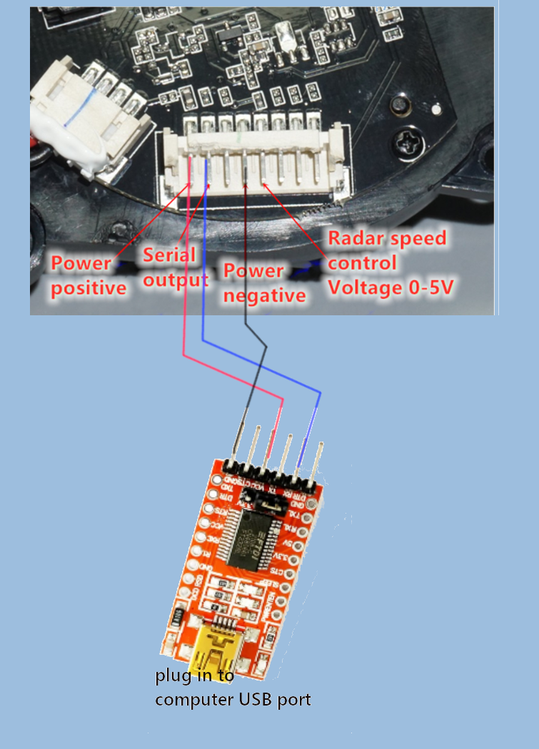
When I bought this LIDAR, I still imagined that I would connect it directly to an Arduino, at least that's what the Swiss blogger did, where he had a completely different converter, which I also bought, but which is now still awaiting its destiny while lying around among in the heap of my other electronic stuff. But actually this connection directly to the USB port of the computer is at least for me already easy, because the programming tool Visual Studio Code, and python is pre-installed and reasonably familiar to me. The required plug-in module for the computer's USB port can be found at the following link. According to wikipedia TTL stands for Transistor-Transistor Logic, the name means that transistors, bascially 2 circuits in series both amplifiy and performs logical functions. I don't think it means anything, but it's a converter between the USB port and the RS232 serial signal. I still remember that the abbreviation RS232 appeared with the C64 computer. Link:
There is also a reference on Lidar's sales site to find the right program snippets for decoding the signal. This Discord discussion group came into the public eye because an American posted secret photos and other information about the war in Ukraine, apparently just bragging how much he knew. On that specific channel named mb_1e2tydlidar-s4b there is a man called VIDICON who has been investigating this lidar deeply. Apparently the seller has not provided any documentation about this device. Not to say that it is not untypical of Chinese vendors. VIDICON apparently has the appropriate signal analysers to gradually work out what all the its and bytes of data packet means that the device is putting out. Wow, I have great respect that such gurus like VIDICON are around in this world. By the way, even though the code comes from github, that for me it was not exactly a one-to-one, but I had to experiment a bit, what kind of baud-rate it works with, turned out to be 153600. Fortunately my computer already had python installed with VS Code, but I had to add the additional modules pygame, serial, math and enum. I can't remember, something similar like sudo apt-get install -y enum was necessary or maybe the equivalent on a windows machine.
The program as listed here is not exactly the same as the github program, but in addition to baudrate, I changed the pygame command set_at, which produces only a very faint dot on the screen, and replaced it with a rectangle pygame.draw.rect, which is much better visible. I also tried pygame.draw.circle, but it's just too slow, makes a lot of horizontal lines on the screen. I also changed the magnification factor, distancef = distance / 40 then when I want more details to be highlighted, my own face profile as an example, then I set this factor to 3. However, I am quite unfamiliar with pygame and the whole program is like Hebrew to me, especially this class State(Enum). I'll still have to get familiar with it.
LIDAR connection scheme to computers USB port
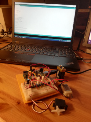
Testing the LIDAR by walking around in my flat
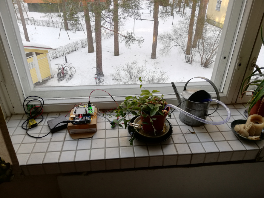
This seems to be a pretty common type of Arduino project. I’m terribly lazy to water my flowers, often forgot for weeks, and I want the flower to be watered automatically with a pump whenever the water runs out. The setup includes an Arduino Uno, water pump, water hose, water level sensor and Arduino adapter card, and a blue relay.
Arduino program code
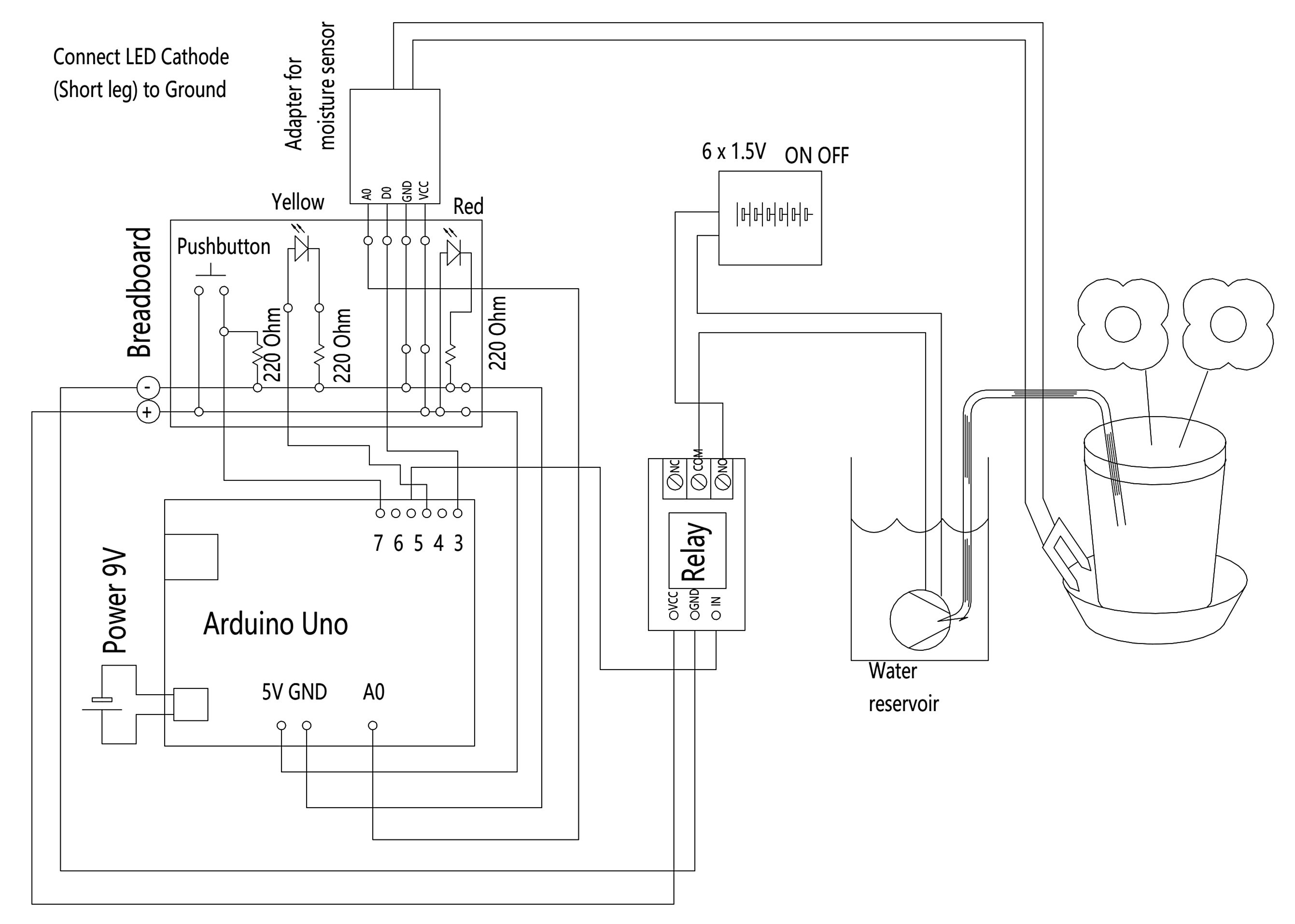
I took some program example from the Internet as a starter. I tried to find a challenge for myself. There is a delay command in the original program example, which prevents the pump from starting immediately the sensor detects that the water level has gone dry. But at that point, the program cycle is interrupted. In my program version, the program cycle is never interrupted, but sensor signal change doesn't cause any immeditae raction, but 2 different counters are triggered and then increased during every program cycle, until a time threshold triggers again. The first counter starts when the sensor state goes from wet to dry. The counter then waits a longer time before the pump starts, because it does not matter that the flower is dry for a short time, but it is more important that the pump battery does not run out because the pump is starting all the time, and then running only few seconds. On the other hand, as soon as the pump has started and starts filling the water pot, the pump must be switched off quickly when the sensor detects the water, otherwise the plate under the flower pot would overflow and the water will spill to the floor and cause damage. Therefore, the second counter shuts off its pump immediately when the sensor detects water in the plate under the flower pot. For the first time I used a relay, so in principle Arduino can also connect the right mains devices, such as a lamp, socket, radiators, radio, etc. it feels very exiting, to hear the relay click! But this still feels a bit dangerous, so all devices at this stage only run on battery. later addition: The problem with the first circuit and program is that the tank from which the water is taken, can be empty. Therefore, when the pump starts, it is necessary to prevent the pump from running continuously and the supply battery of the pump would be discharged unneccessary, even if there is no hope that the pump will add water to the flowers. Because in this case the pump runs empty, and only pumps air. Therefore, when the pump is started, a seperate counter starts, and when the counter has reached the limit value, the pump switches off and at the same time the red LED lights up. Then from the red LED I can see, that I have to add water to the water tank. After that, I press a reset button. The reset button will turn off the red light and puts the pump runtime counter to zero. So the next time the sensor indicates that the flower is dry, the pump will start rotating again. But unless water is added to the tank, the pump will not run as it would be a waste of battery energy. This counter should be so, that within counter time, the reservoir is emptied in any case.
even in this ever so small project, debugging was the most time consuming of all. I was really bothered by the feature of Arduino's built-in Serial monitor that I can't clear the screen there with the "clear" command. From Internet I found a small Python utility that displays the serial port signal to the terminal window and after each cycle the terminal window is cleared with the "clear" command. It makes it much more easy to follow the flow of events.
Originally, I had an women’s bike with well equipped electrics. It had an LED front light and an LED back light with a parking light function. The light is needed only in winter, but in winter the roads are quite choppy due to the snow and ice, so that the tail light came off in the vibrations, after only few months. Moreover, I always replace the hub generator for the summer with a hub without generator, which is running with less resistance. During that I also have to remove the headlight. But unfortunately I broke it during this changing operation. Only then did I notice that in that LED light is all the built-in electronic circuits that convert the current from the hub generator into a DC suitable for the LED light. I was thinking first of buying an identical LED that can be connected directly to a Hub generator, but I couldn’t find anything in Internet (so there are lots of lights but nothing which clearly states, that it can be connected to a hub generator). But I found a guide to the USB charger online. And there are quite a lot of LED lights available for USB charging. I had the idea, I could charge my smartphone, too, on the longer cycle trips, so it is more universal. I ordered parts online (Farnell, Conrad) and soldered together on the kitchen table. And I also ordered a USB LED light from China, but they didn't deliver the right type, so I used a normal LED flashlight instead, and clamped the cable directly to where the battery would sit. One winter, I cycled with it, but now I've lost it again the LED light. So I have to look around again for a light. PS: Now I ordered one model from Ebay: Union LED Headlight Sidelight Sensor Lux for Hub Dynamo".
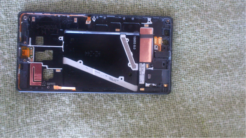
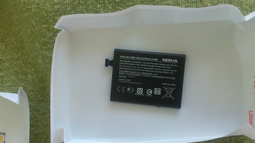
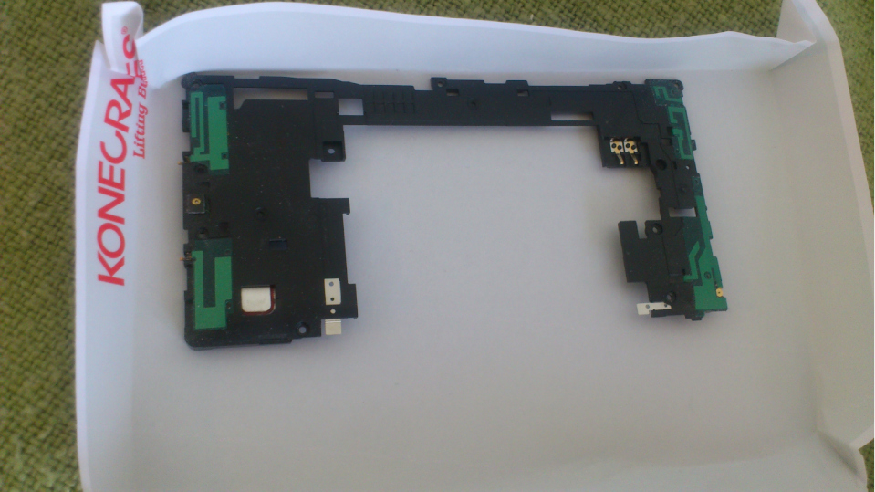
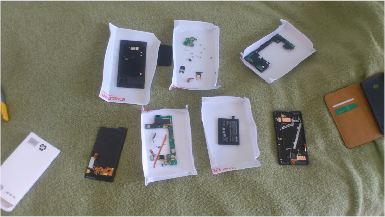
I was sometimes proud of my Lumina smartphone. But it didn’t take long and it dropped to the floor. And as the sandwich always drops with the butter side to the floor, so this handset crashed with its face to the floor. It happened maybe 2 weeks after buying, I couldn’t stand the idea of buying a new phone right away. Fortunately, a coworker advised that these smartphone screens can be purchased online, and repair is possible DIY, because with screen comes also the necessary tools. That's what I did. Yes, there were a few moments of horror. It needs a heat blower to loosen those double-sided tapes. And you have to be really patient an no use of force.
Many thanks to to youtuber, I was able to disassemble the smartphone
Fortunately, I still had another phone available during that time, so I was able to watch the instructions over and over again while tackling the diverse problems
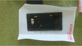
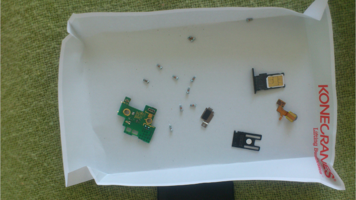
The connectors are really made of microscopically small pins. After the repair I had to press the smartphone tight at the place of one connector, to get the picture on the screen back. The motor for vibration is size of a russin. The battery is glued with a double-sticking tape, and only by heating it with a hot air gun and at the same time using the plastic tool to get it out, it was getting loose very slowly. Also the screen was really tight and getting it loose took maybe half an hour. And of course, the new screen has to be glued with two side tape again, so I have to cut 2mm strips out of a normal tape roll.
In the library I stumbled upon Tero and Kimmo Karvinen's book Sulautetut = Embedded. Reading the book didn’t cause any immediate enthusiasm, but it was a bit like start of a slowly smoldering fire in my mind. Later I notices that the evening college was organizing a course on it. The course did get enough participants, but I bought this starter kit. Let's see where it will lead to.
I've made time-delay videos on my smartphone. The obvious problem is that the time delay cannot be set, and another is that the camera still needs to be standin there all the time, and somebody might steal it. The setup requires: 1. ESP32CAM ( for instance Alibaba) 2. any kind of 5V power supply pack (I bought from Tokman) 3. USB cable, cut it and use only the male connector (Clas Ohlson) 4. Two wires, one side female connector suitable for these ESP32 CAM needle-like outlets, the other side crocodile clamps. 5. SD card reader + compatible USB cable 6. SD card. I found online instructions on how to make a little box for ESP32 with a 3-D printer. I don't have this, but it also works with a plastic box from my bike repair kit. I glued various wooden pieces to the inside of the box with glue, so that the ESP32 fits neatly inside. I still have to carve small notches into the wooden pieces with a knife, because otherwise the Rst and flash button will interfere.
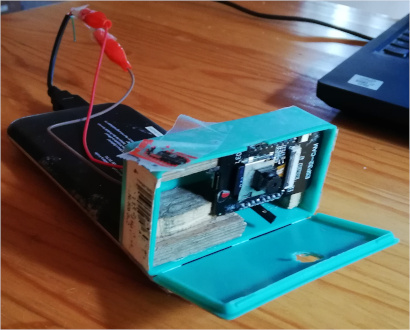
At the back of the box I made a hole for the 5V and for the ground cable, their plugs are unfortunately a little too long. The frontcover has the hole for the camera, it can be done with a drill or knive. The ESP 32 needs to sit pretty tight, otherwise it will sag and the picture will be skewed.
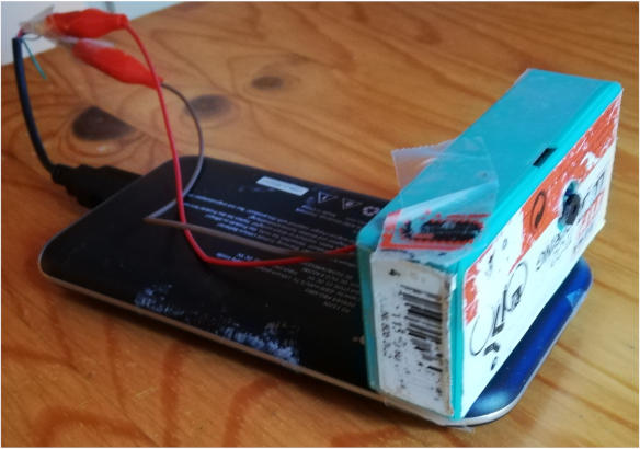
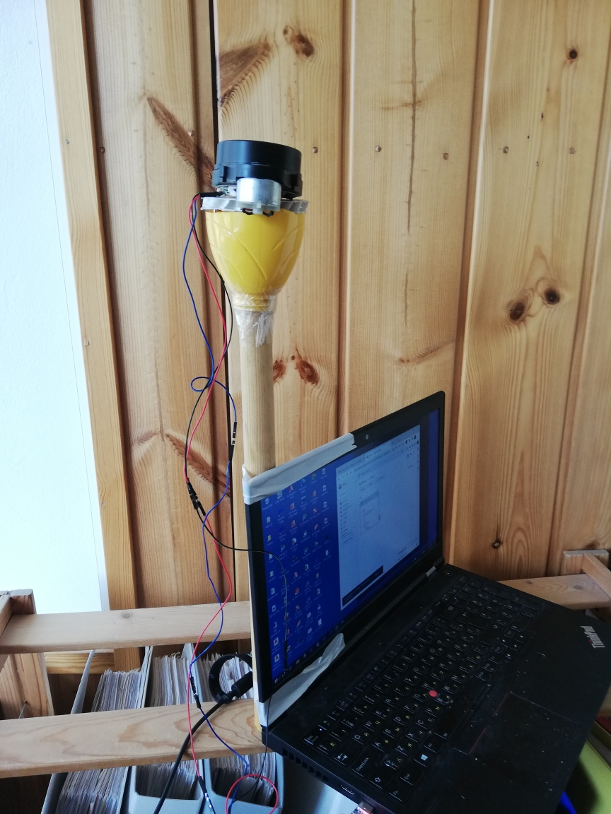
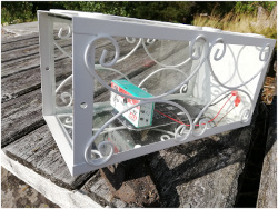
I was afraid that rain will happen during shooting, so I put ESP 32 inside the windshield of a candlelight. The wind was always pretty strong, the windshield can also prevent the ESP32 CAM from flying away by the wind.
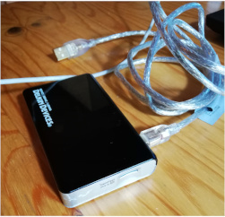
After the shot is done, I take the ESP 32 CAM inside the house and stop it, either via Wifi or just pull the 5V cable off, take out the SD card and read the SD card through this card reader. That card reader was a leftover of an old pixel camera, which I had sometimes. But the cable was special, with a narrow USB mini-A connector.
This guide is now a bit like for myself.<br />
Remember:<br />
Mobile Wifi must be turned on. Settings -> Wireless and Networks -> tethering and Portable hotspot-> Portable Wifi hotspot<br />
The computer must be connected to the mobile's Wi-Fi Ctrl + X -> Wifi -> show available networks -> Connect<br />
The Wifi address only works with Firefox browser at http://192.168.43.209/<br />
(no https)<br />
Launch the Arduino ino program. Inside the program also adjust Wifi ssid and password correctly.<br />
<br />
load the Timelapse program<br />
<br />
Connect the ESP32CAM to the computer with an USB cable. The ESP32CAM device does not have problems even if it is connected to the power supply at the same time. (the battery voltage may be less then USB cable voltage) <br />
<br />
Check Port COM3 or COM7<br />
<br />
Arduino Tools-> check all settings correct .<br />
<br />
At least:<br />
<br />
Wifi101 / WiFiNINA Firmaware Updater<br />
<br />
Board ESP32 Wrover module<br />
<br />
Upload speed 115200<br />
<br />
Flashmode QIO<br />
<br />
Partition scheme Huge APP (3MBNo OTA / 1MB<br />
<br />
Core debug Level .None<br />
<br />
Programmer AVR ISP<br />
<br />
Press upload in Arduino.<br />
Hold down the RST and flash pushbuttons. When the upload starts, i.e. when .... ---- ....---- appears on the program's command screen, release the rst button. Then the blue LEDs should go on.<br />
<br />
This will rarely work first time. Only when the blue LEDs turn on, do things start to work out.<br />
<br />
At that point, I flip between COM 7 and COM 3. Oddly enough, the program always shows the ESP32 Wover Module to COM7 or COM3. As I write this, it was COM7.<br />
<br />
I still open the serial monitor. and I press the reset. In this context, the size of the SD card should also be shown in the monitor.<br />
<br />
SD Card Type: SDHC<br />
SD Card Size: 32000MB<br />
<br />
Total space: 31936MB<br />
Used space: 0MB<br />
.........<br />
WiFi connected<br />
Starting web server on port: '80'<br />
Starting stream server on port: '81'<br />
Camera Ready! Use 'http://192.168.43.209' to connect<br />
<br />
Then only the Firefox browser can be opened and enter its address there.<br />
Then I plug in the 5V and GND wires and unplug the USB cable, and try to see if the stream still works.<br />
<br />
I set the timelapse to 3000-6000 ms.<br />
Resolution CIF (400x296) when I put it more closely, there were unpleasant disturbances in the image.<br />
<br />
I take everything, my computer, cell phone, and ESP 32 Cam to the place where I intended to make the time delay
video. <br /> Then I place the ESP CAM as horizontally as possible, and for this I use the still image function, and make sure the image is correct. The V-flip may also needed. Only then do I press the timelapse image.<br />
<br />
You can then let it running, many times I leave it out for an hour. I take back my computer. The radius of the Wifi antenna may reach 10m. During the timelapse, no Wifi necessary
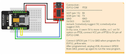
Now there is another ESP32: it does not have a built-in opacity device, but an external device called CP2102 USB to TTL Serial Converter Module It also comes with a Wifi antenna, thanks to which the range is already 15m or more. In the programming phase, the cables must be as shown. The program will be transferred from the Arduino IDE at the same time as before. But then after the program is transferred, you must first disconnect the cable that connects GPIO0 and GND. Then I press reset, and then I get to read the device address on the Arduino serial monitor, which is http://192.168.43.40. After that I can also take the RX and TX iodines off. The device only needs 5V and GND to work. First I put the Cell Phone Settings- Tethering & Portable hotspot - Portable Wifi hotspot - ... ON. Then I put in the smartphone Web Browser first "New incognito tab" in the top right corner, where are three dots. Then in the browser address field, I enter the address of ESP32 cam device. If the device is turned on, you should already have see camera image. If not, I still press the reset button. And then I can start a series of time delays on my cell phone. That's how it should be working.
When I install ESP32 for programming, I have to go to Arduino IDE Tools manage Library, and there I should be able to find bitluni ESP32Lib

File- Preferences
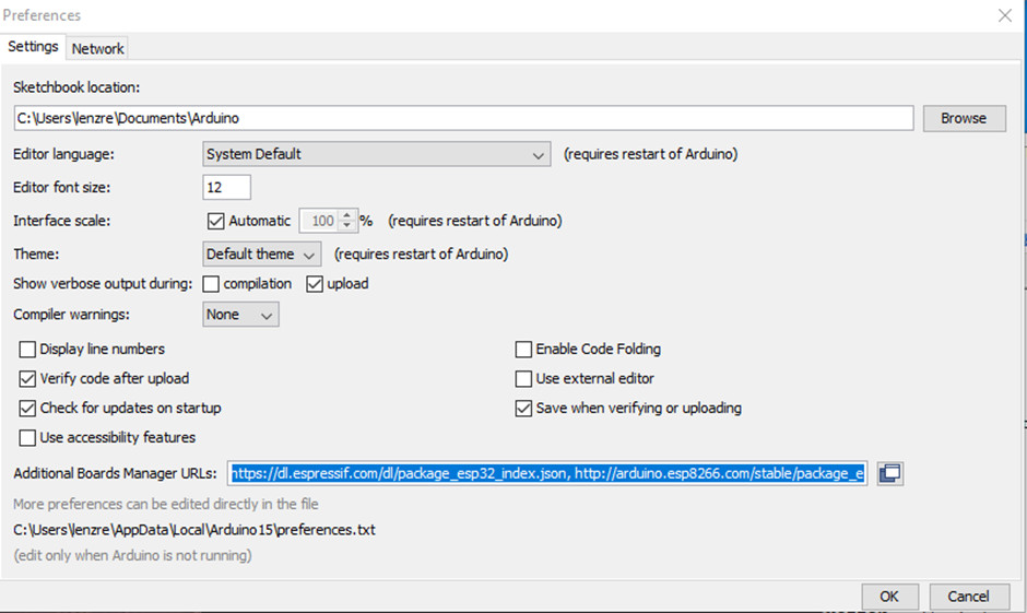
https://dl.espressif.com/dl/package_esp32_index.json/
http://arduino.esp8266.com/stable/package_esp8266com_index.json/
Upload speed 115200
Flashmode QIO
Partition scheme Huge APP (3MBNo OTA /1MB
Core debug Level .None
Programmer AVR ISP r this, I will be able to select in tools Board Board ESP32 Wrover module
]]>