Foreword: By April 2026 , I was getting ready with a newer version of this compass belt. The basic principle of the compass belt is not changed, but the motor are supplied directly from the battery, so the Microprocessor doesn't have to deliver the large current by itself. The microprocessor is replaced by a smaller model. There are only 16 motors. The link to the new project https://github.com/ReinhardLenz/compass-belt-seeeduino-XIAO can be found below. The new project is working. The compass belt described here is also working fine, (the biggest drawback is the bigger box) so I leave the text as it is, but I will not update it anymore and keep both versions seperate. Under this descriptions are some good description of the construction process, which I will not repeat in the new project, so I think it is good to keep this text as it is.
Many migratory animals, such as birds and fish, are said to know the compass directions when migrating, sometimes over very long distances, night or day, and often in very bad weather.
For humans, this kind of knowledge may be needed, for example, when picking berries in an unfamiliar place or simply when losing one's sense of direction.
A compass belt is a belt that helps you know where north is without looking at a compass. It has small vibration motors and a sensor that detects the Earth's magnetic field. When you wear it, the motor facing north vibrates slightly, giving the wearer an "intuitive" sense of direction.
Why is this cool? Imagine you are in the forest picking mushrooms at dusk and you lose your bearings. With this belt, you will always feel the "tingle" of the North Pole, which helps you stay on track without maps or compasses.
I ordered the electronic parts online for about $60.
Then I sewed and soldered the vibration motors onto a stretchy fabric belt.
I added a plastic buckle and used a textile tube to protect it.
As an orienteering enthusiast with a basic knowledge of electronics, I found this project both fun and useful. Whether you're exploring new trails or just love cool gadgets, the Compass Belt can be a great companion!
Direction adjustment
Adjustment knob to adjust the direction 0... 360 degrees
vibration modes
Double-click to switch between continuous and intermittent vibration. Single-click to switch between 1, 2, 3, or 4 seconds. Long press to quickly test that all vibrators are working.
Smart sensor
A self-calibrating magnetometer that recognizes whether you are walking, cycling, or standing still.
Battery-powered for hours of navigation.
Two batteries provide approximately 3 hours of use.
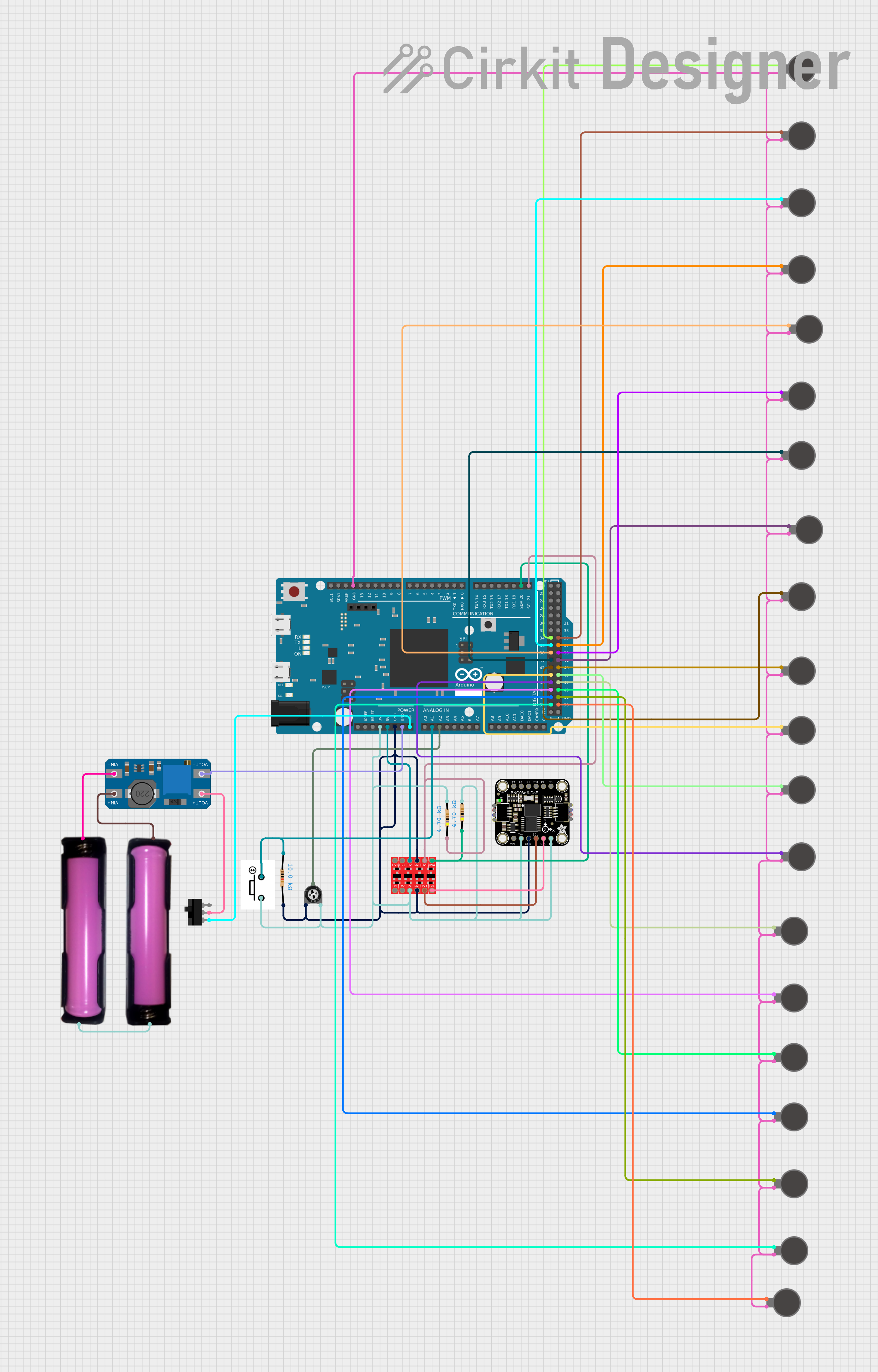
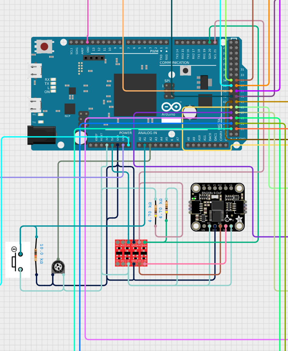
This circuit is designed to interface an Arduino Mega 2560 or Arduino Due with various components, including a Bi-Directional Logic Level Converter, a Trimmer Potentiometer, multiple Vibration Motors, an Adafruit BNO085 9-DOF Orientation IMU Fusion, and other components. The circuit is powered by 18650 batteries and includes a toggle switch for power control. The Arduino Mega 2560 or Arduino Due is programmed to control the vibration motors based on input from the IMU and other sensors, providing haptic feedback about north direction.
A microcontroller board based on the Atmel SAM3X8E ARM Cortex-M3 CPU.
Features multiple I/O pins, PWM outputs, and communication interfaces.
Used to safely interface between different voltage levels, such as 3.3V and 5V.
A variable resistor with a resistance of 10k Ohms, used for adjusting voltage levels.
Two resistors with a resistance of 4.7k Ohms and one with 10k Ohms, used for current limiting and as pull-up resistors for the I2C bus.
Multiple small motors used to provide haptic feedback.
A sensor module that provides orientation data using a combination of accelerometer, gyroscope, and magnetometer.
Provides power to the circuit.
Used to control the power supply to the circuit.
Used for user input to control the circuit's behaviour.
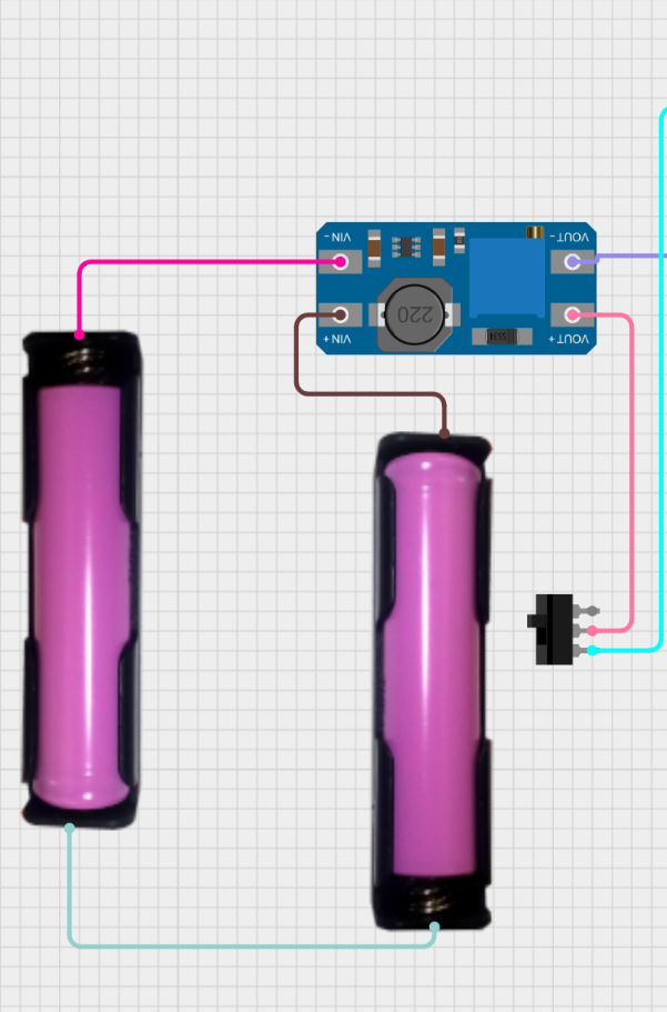
A DC-DC step-up converter used to boost the voltage from the battery.
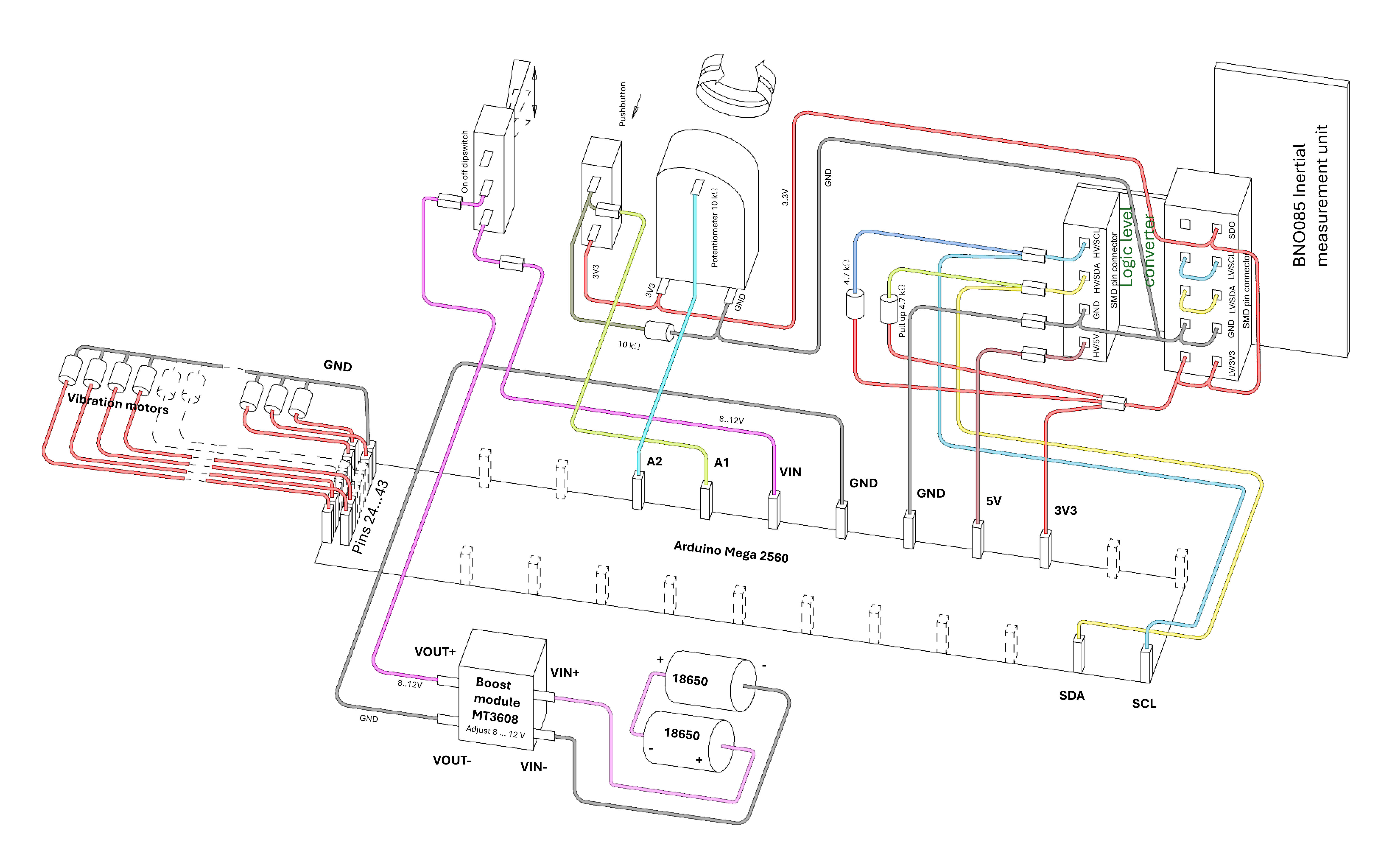
A2: Connected to the wiper of the Trimmer Potentiometer.
A1: Connected to pin1 of the Resistor (10k Ohms) and pin2 of the Push Button.
D20/SDA3: Connected to HV4 of the Bi-Directional Logic Level Converter.
D21/SCL3: Connected to HV3 of the Bi-Directional Logic Level Converter.
5V: Connected to HV of the Bi-Directional Logic Level Converter.
GND: Connected to GND of the Bi-Directional Logic Level Converter, Resistor (10k Ohms), Trimmer Potentiometer, Adafruit BNO085, Boost module MT3608 and Vibration Motors.
VIN: Connected to L1 of the Toggle Switch.
D26 to D45: Connected to the positive terminals of various Vibration Motors.
GND: Connected to GND of the Arduino Mega 2560 or Arduino Due and other components.
HV: Connected to 5V of the Arduino Mega 2560 or Arduino Due.
HV3: Connected to pin1 of the Resistor (4.7k Ohms) and D21/SCL3 of the Arduino Mega 2560 or Arduino Due.
HV4: Connected to pin1 of the Resistor (4.7k Ohms) and D20/SDA3 of the Arduino Mega 2560 or Arduino Due.
LV: Connected to pin2 of the Resistor (4.7k Ohms) and leg2 of the Trimmer Potentiometer.
LV3: Connected to SCL of the Adafruit BNO085.
LV4: Connected to SDA of the Adafruit BNO085.
Wiper: Connected to A2 of the Arduino Mega 2560 or Arduino Due.
Leg1: Connected to GND of the Bi-Directional Logic Level Converter.
Leg2: Connected to LV of the Bi-Directional Logic Level Converter.
10k Ohms: Pin1 connected to A1 of the Arduino Mega 2560 or Arduino Due, pin2 connected to GND.
4.7k Ohms: Pin1 connected to HV3 and HV4 of the Bi-Directional Logic Level Converter, pin2 connected to LV of the Bi-Directional Logic Level Converter.
Positive Terminals: Connected to D26 to D45 of the Arduino Mega 2560 or Arduino Due.
Negative Terminals: Connected to GND of the Arduino Mega 2560 or Arduino Due.
3.3V: Connected to LV of the Bi-Directional Logic Level Converter.
GND: Connected to GND of the Arduino Mega 2560 or Arduino Due.
SCL: Connected to LV3 of the Bi-Directional Logic Level Converter.
SDA: Connected to LV4 of the Bi-Directional Logic Level Converter.
connected in series, + pole of first is connected to + pole of the second
- pole of First 18650: Connected to VIN- of the MT3608.
+ pole of second: Connected to VIN+ of the MT3608.
L1: Connected to VIN of the Arduino Mega 2560 or Arduino Due.
COM: Connected to VOUT+ of the MT3608.
VIN-: Connected to - pole of the first 18650 Battery.
VIN+: Connected to + pole of the second 18650 Battery.
VOUT-: Connected to GND of the Arduino Mega 2560 or Arduino Due.
VOUT+: Connected to COM of the Toggle Switch.
Pin1: Connected to LV of the Bi-Directional Logic Level Converter .
Pin2: Connected to A1 of the Arduino Mega 2560 or Arduino Due and connected to pin1 of 10 k Ohms resistor.
The Arduino Mega 2560 or Arduino Due is programmed using a sketch that includes several libraries for handling the haptic belt, compass, and button inputs. The code initializes the IMU sensor and sets up the vibration motors for haptic feedback. The main loop reads the button states and updates the compass heading based on sensor data or serial input. The haptic belt is updated to provide feedback based on the compass heading.
Github Compass beltLibraries: Includes custom libraries for handling the haptic belt and compass, as well as standard libraries OneButton.h for the button clicks, Wire.h for I2C communication and Adafruit_BNO08x.h for the BNO08x sensor.
Pin Configuration: Defines pins for buttons and vibration motors.
Sensor Initialization: Initializes the BNO08x sensor and sets up the desired reports.
Main Loop: Continuously reads button states, updates the compass heading, and controls the haptic belt based on the heading.
zoom in to the important parts of the principal drawing
Zoom in to the boost converter part in the principal drawing
a diagram of the circuit. The picture shows an Adafruit BNO08x, but I actually have a BNO085 slimeVR. The interfaces are the same. Protection freewheeling diodes could be used to eliminate a sudden voltage spike in the inductive load when the supply current is interrupted. But here the current spike is apparently small enough, the Arduino has not yet broken.
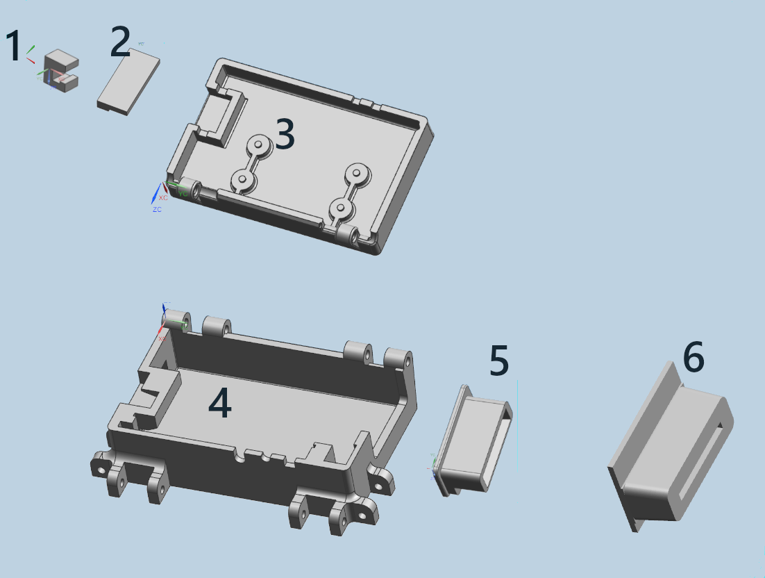
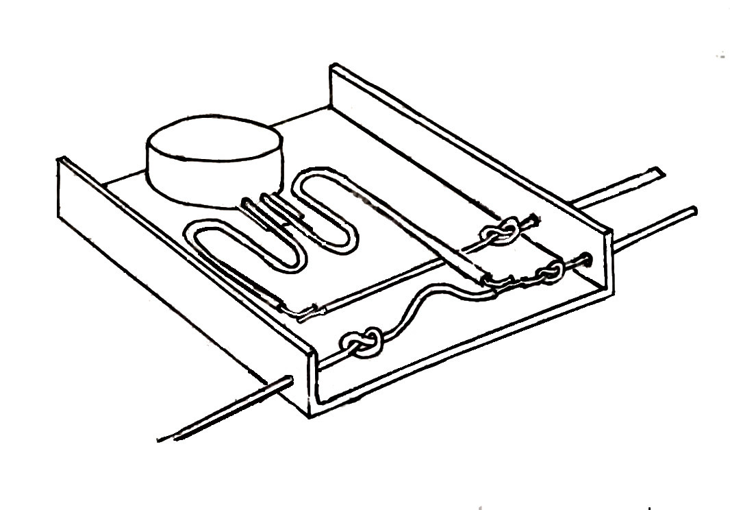
The box consists of 6 different parts: 1: slider closer. 2: overhang part for closing the slot. 3: Upper box 4: lower box. 5: inner cable gland. 6: Outer cable gland.
The slider (1) is designed like a clamp. It can move back and forth in a slot. There is a position in the slot where the box can be opened. However, if the slider is pushed so that the clamp-shaped slider grips around the tongue, the box can no longer be opened. The slot is created by gluing part (2) to the top of the box (3). However, when gluing, the slider (1) must already be in the slot, because the slider cannot be inserted after part (2) has been glued in place. This has the advantage that the slider can never be lost. The upper part of the box (3) is connected to the lower part of the box via two hinges. I used 4 mm diameter welding wire for this. The cable entry consists of two positions (5) and (6). The smaller flange (5) is pushed into the larger flange (6), but first you put adhesive putty in the gap. This putty presses the flat cable together, creating a good seal. It also prevents the plugs from coming out of the socket when there is some tension pulling on the flat cable.
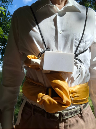
The box has four connections for elastic bands, two on the side and two on top. The best position for the box is on the chest. When the box is on the chest, it is also very easy to operate the potentiometer for adjusting the direction, toggle on off switch, and push button. In my experience, it is not enough to hold the box on the side with a belt while running; you also need “suspenders” made of textile elastic bands that are looped around the arms. These “suspenders” are threaded into the vertical buckles. These suspenders prevent the box from sliding down due to the jolts while running.
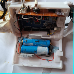
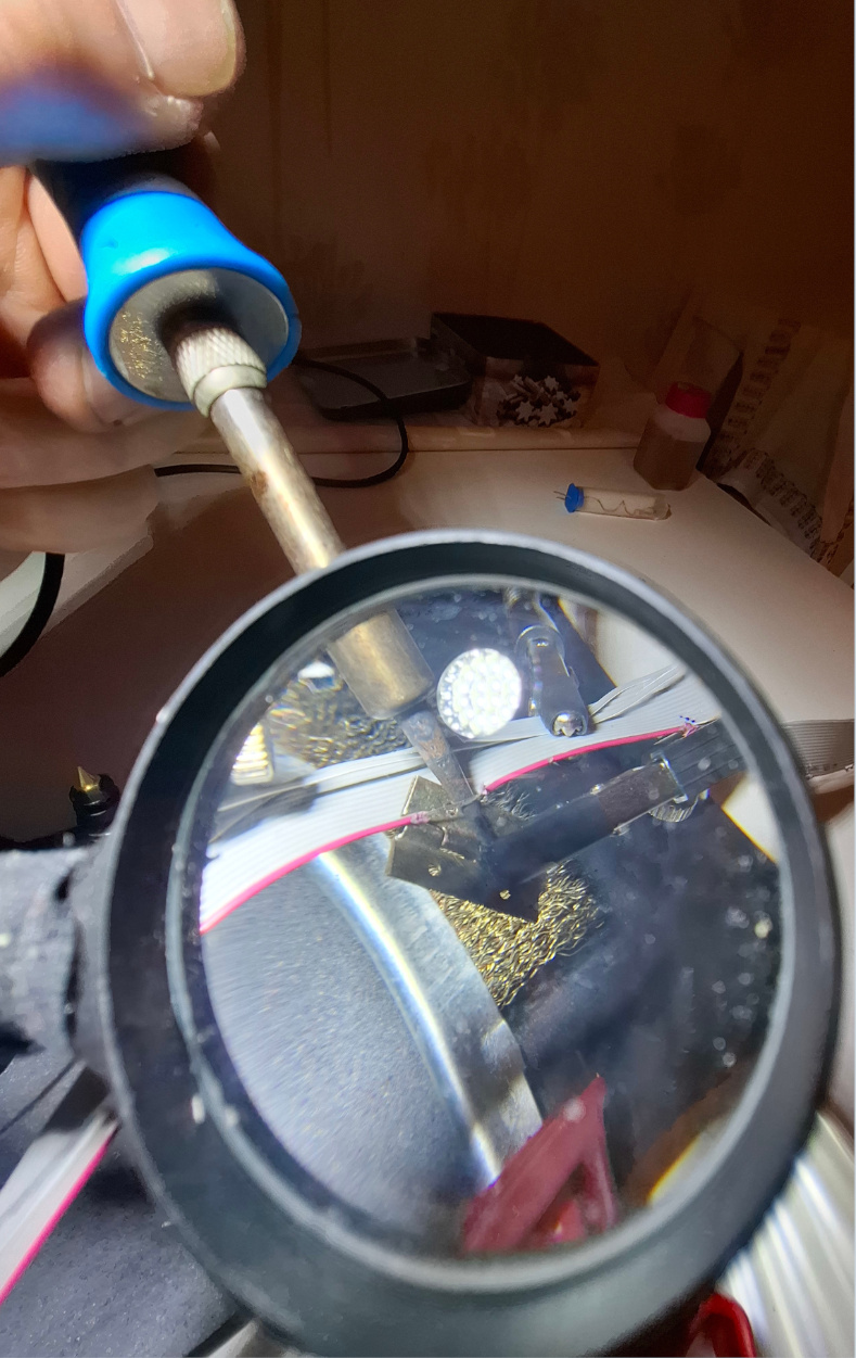
in this picture you can see the 3D printed case opened from the front. Arduino in the middle, connectors for the vibration motors on the left. Here you can see that the ground wire has a small " elbow " in the wire terminal, because the GND connector is seperated in the connector row. On the top right you can see the BNO085 slimeVR IMU sensor. The blue wire is the SCL (clock) wire, the yellow wire is the SDA (data) wire, but the wire colors are different from the diagram. At the bottom center you can see the battery compartment, and at the top you can see the soldered switch plate. The Arduino wires are all connected with a Dupont connector, so that all power can also be completely disconnected. The wires are "glued" to the edges with adhesive putty, so that all the stuff can also be temporarily removed from the case. The sensor must always be approximately horizontal to give the correct air direction.
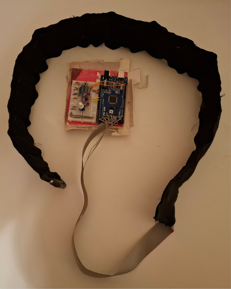
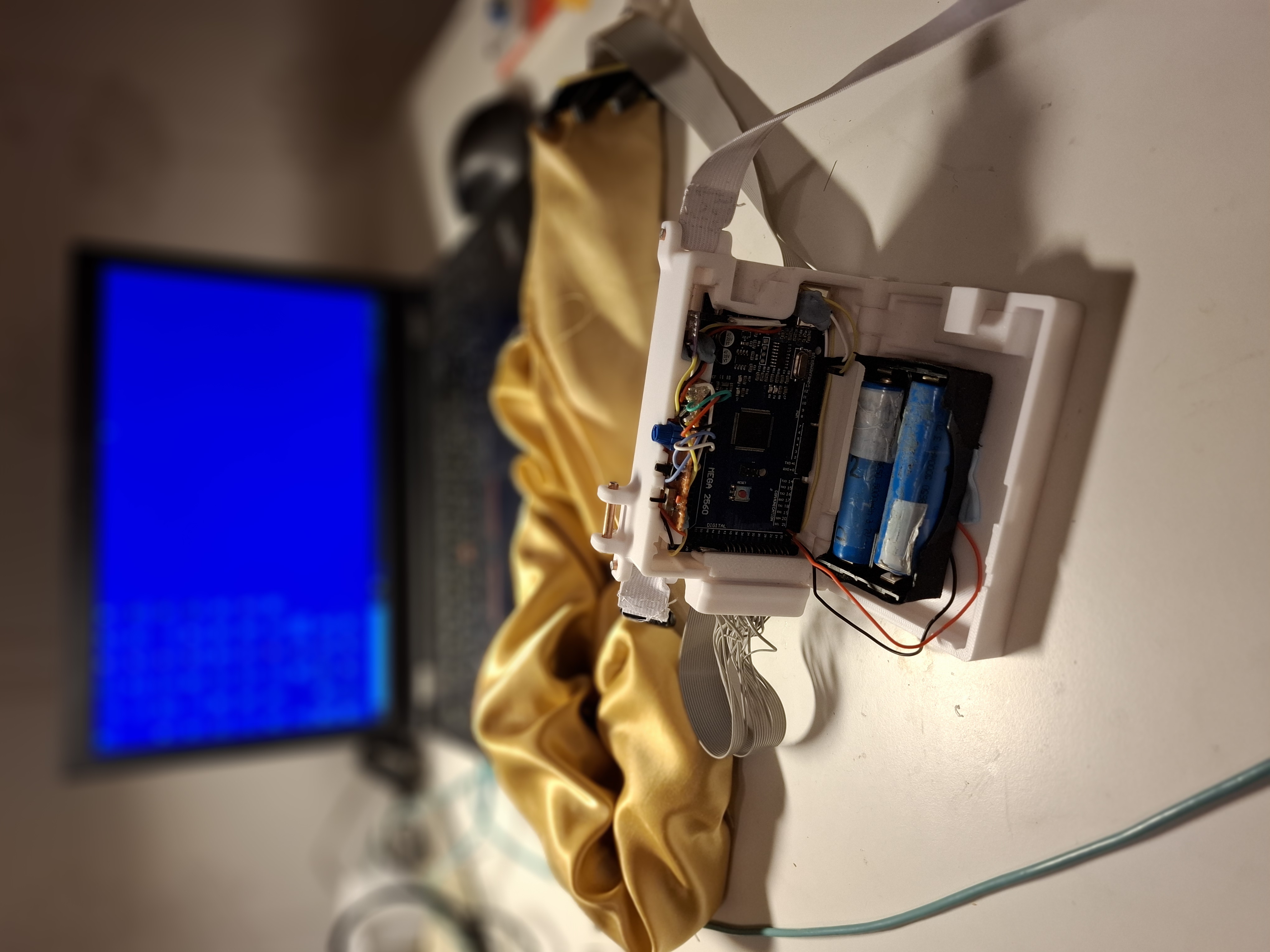
Here you can see the compass belt in its entirety, in front of the electronics housing, from the left the ribbon cable goes out to the vibration motor belt, which is protected by a yellow cloth. The enclosure itself I put my own stretchy textile tape around the belly, or alternatively it can then also be put in a trouser pocket. Between the holster and the actual belt there is about a 30cm loop, so that the holster can also fit in a trouser pocket, belt pouch or even a rucksack. This holster has two rubber band attachments, one for horizontal position, and one for vertical position. I find that the horizontal position is better for running, as the holster flops less. At first I tried attaching the case directly to the vibration motor belt, but that takes up too much space there, and the vibration from the vibration motors under the case gets distorted, and the rubbing between the case and the motors could perhaps tear the connectors and wires.
The compass belt dressed with a yellow synthetic fabric cover. This fabric is thin and smooth, so it dries quickly, and can also be taken off if you want to put it in the washing machine. Orienteering is sweaty and your body is constantly in contact with wet and dirty branches and twigs. The fabric must not be felted, where tiny fibre ends protrude from the fabric acting like little hooks to attach themselves to small cracks in objects, hidden cables and small plugs, causing small kinks in the cable or the plug to get caught in the fabric fluff. The electrical box must be fastened with its own stretchy textile tape. Both straps here are comfortably tight on the body, so that the whole thing works in orienteering too. The cable between the holster and the belt is now unnecessarily loose, it could be shortened with a rubber strap. The electronics housing must not be allowed to fly around, because the sensor measuring its own position in three-dimensional space would then give a false signal. In principle, the sensor will compensate for any tilt, but as a general rule it should be in a horizontal position.
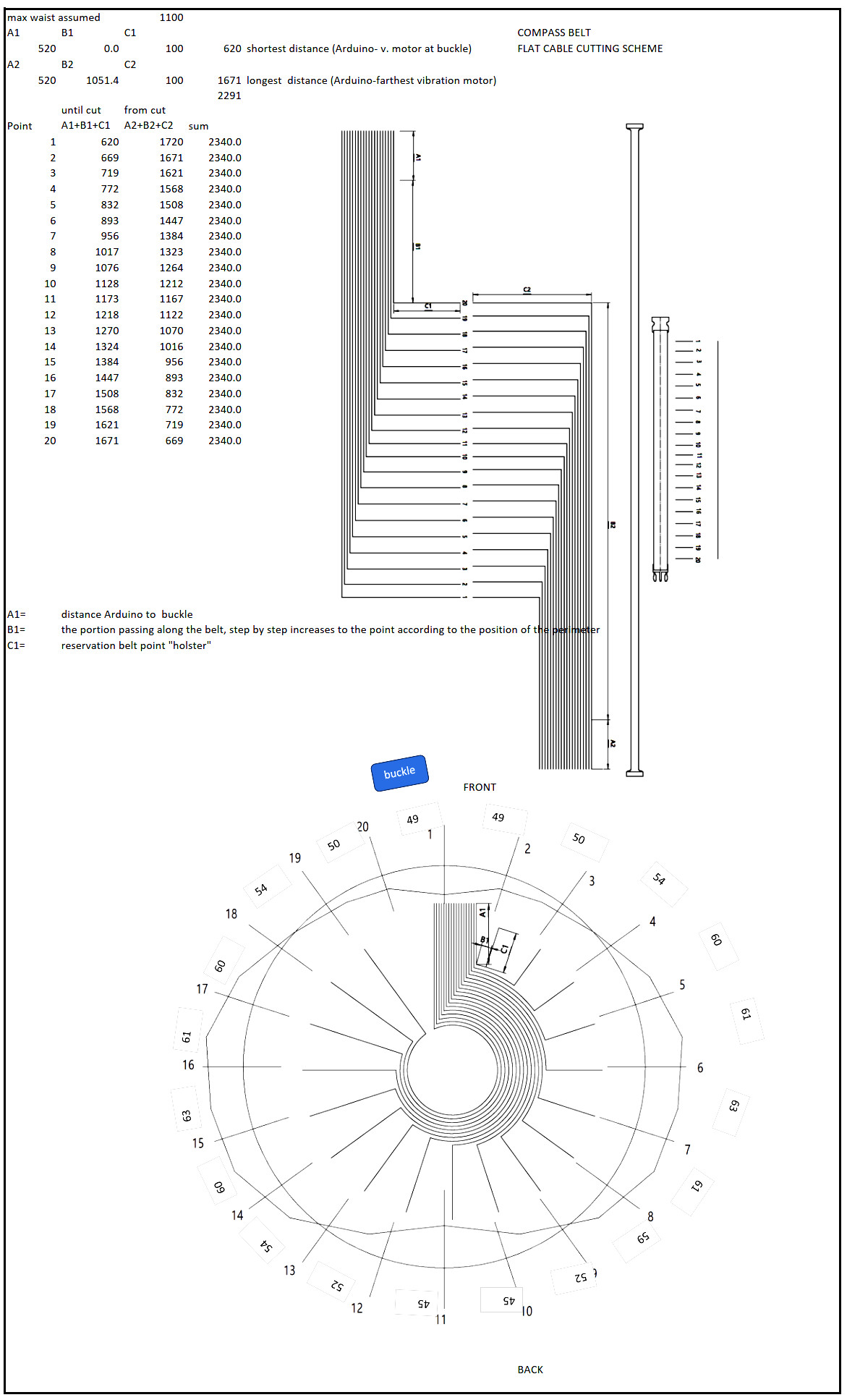
I am not happy with single wires from the arduino to each vibration motor. It creates a mess. Flat cable solution seems to be the cleaner solution. The distance from the bucke should reflect more the true directions, but as the waist of the human is not true round, but more like an ellipse, adjust the distances between the motor points. In case, other people with bigger waist want to use the compass belt, I use a waist circumference of 110cm. The point is, I want to make 2 vibration belts, so I do everything so , that I get 2 identically cutted flat cables. Everything is symmetrical around the center mark. All the cable ends I furbish with dupont connectors, and - very important - I test all cables, to be able to know, that there are no faults, and each and every wire is conducting from connector to connector.
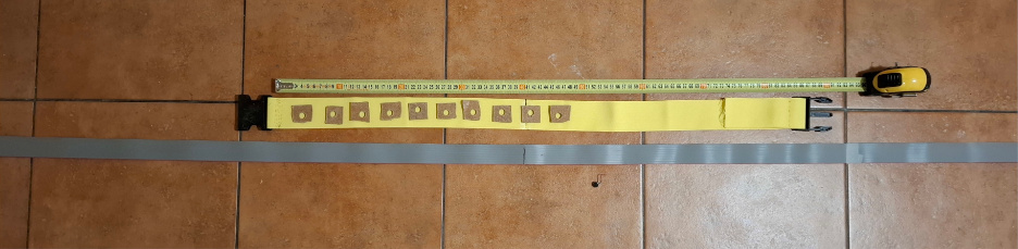
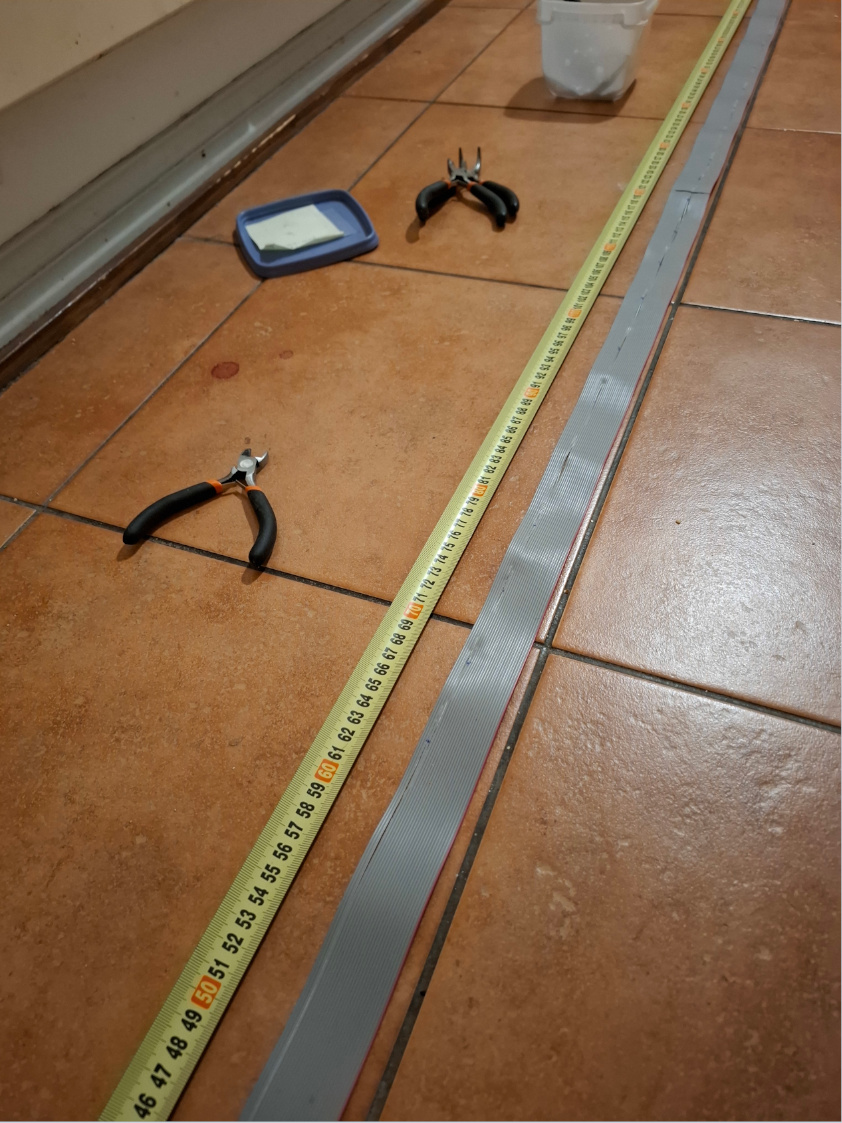
The flexible textile band with sewed on buckle, a tape measure and the flat cable laid on the ground. I mark the middle point. On the flexible textile band, there are trial "nests" for the vibration motors, laid down in the distance.
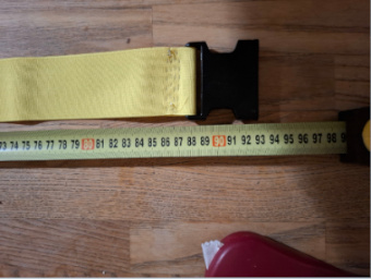
The end of the female part of the buckle. In fact, the buckle is wider then the normal distance between two vibration motors, so there will be some mistake.
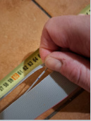
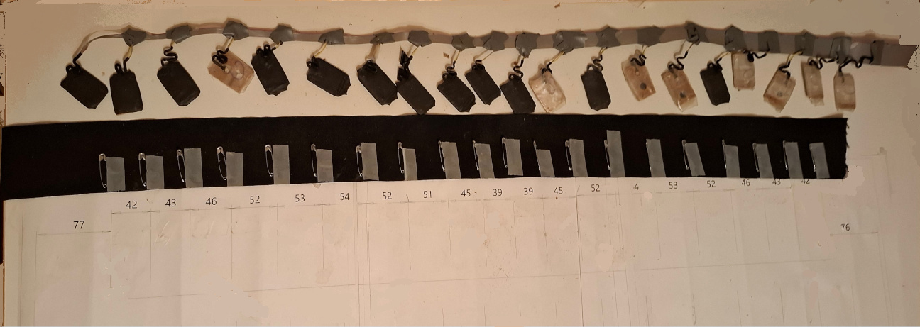
The ends of the flat cables are taped to the floor, so the flat cable is stretched straight. The number of wires on the flat cable is 26, so I leave the outer 3 wires without a cut. The cut point is marked first with felt-tip pen according to the table with cut length. Then, after all marks are done and also checked (from both sides, it should be symmetrical)
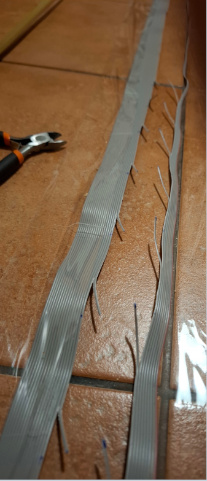
After all single wires are marked, I use a knife to slit the flat cable around the marked spot. I go through all the marked points.
This is the last stage. When the slittling has been done, continue the slitting so that finally the both symmetrical cutted flat cables come apart. Finally make the cuts with cutting pliers.
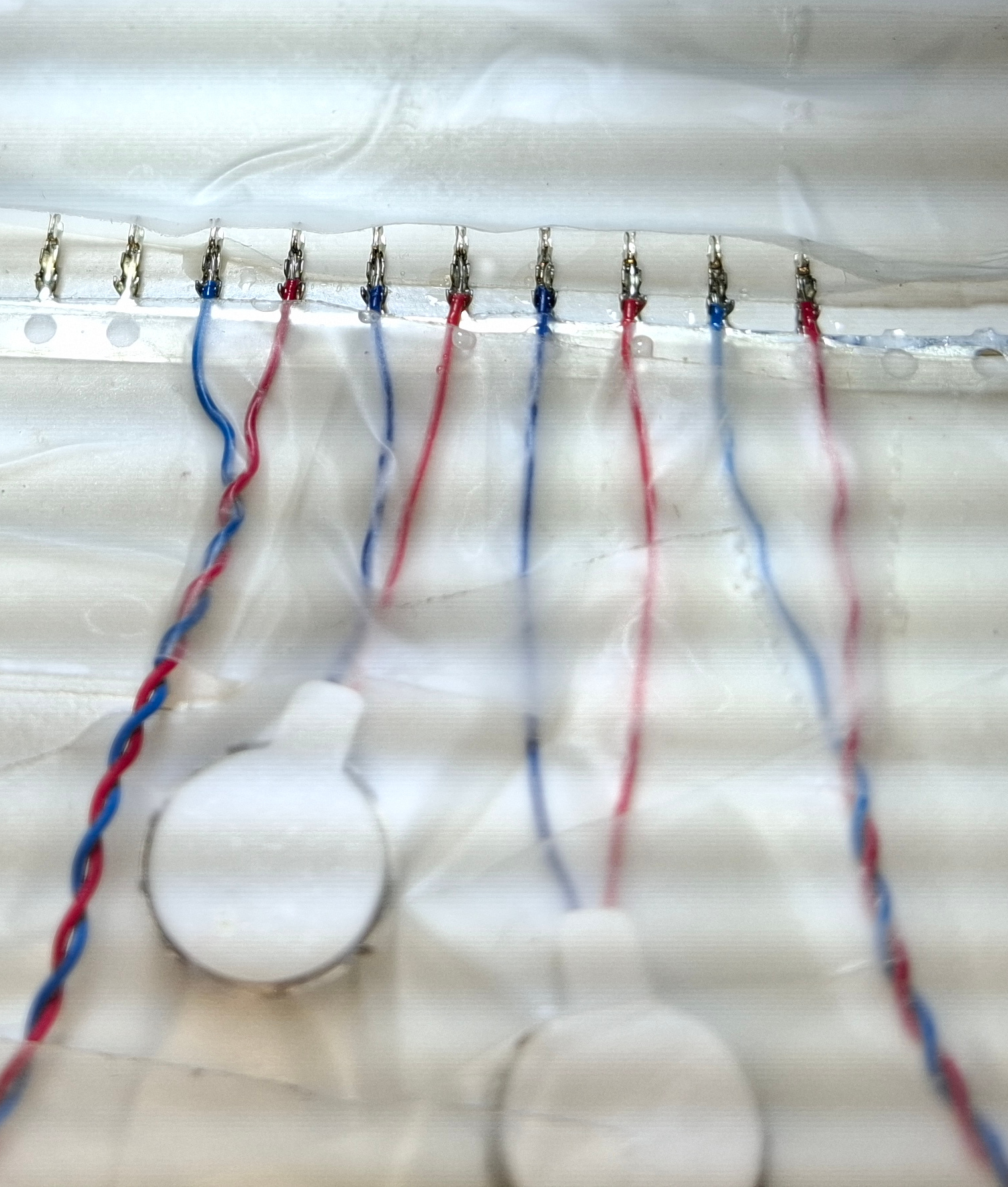
The vibration motors come with JST-SH male connectors. I therefore purchase the appropriate female connectors. These need to be soldered. The connector pins are very small.
It is better to use only a little tin to keep the wire strands as flexible as possible. The soldering point is more brittle and does not take as much bending.
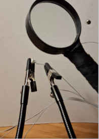
I scraped open the earthing cable with a hot soldering iron under a magnifying glass. I firmly clamped the flat cable with the stand and the clamps. I pushed a piece of sheet metal into the gap between the earthing cable and the other cable as a base. Then carefully scrape away the cable sheathing with a hot soldering iron, taking care not to break off the strands. Also run the soldering iron under the strands. I stripped the connecting cables all together beforehand. When soldering, clamp the wires firmly and solder under a magnifying glass. Once you have managed to get the first solder joint right, the next solder joints are much easier because you only ever have to move the cable.
It is clear that soldered joints break off easily if a cable is constantly exposed to slight bending back and forth, as will certainly be the case with a compass belt. That's why I glued all the soldered joints firmly with epoxy glue (2-component adhesive). So first I wrapped a scotch tape around the plug to form a kind of trough. And then all the cable ends with the plugs are firmly glued to the table with Scotch tape so that nothing can move. Then I mix the epoxy glue and fill all the solder joints as well as I can with epoxy glue.And then I wait a day for everything to set. The next day I remove the Scotch tape and wrap insulating tape around the two conductors.
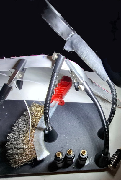
the picture shows how the flatcable is attached with two clamps. Below, a wire brush, which I used to remove the melted plastic from the soldering iron. Supporting the stable soldering iron with another bendable goose neck. I first look past the magnifying glass to make sure the soldering iron is roughly on target, then look through the magnifying glass.
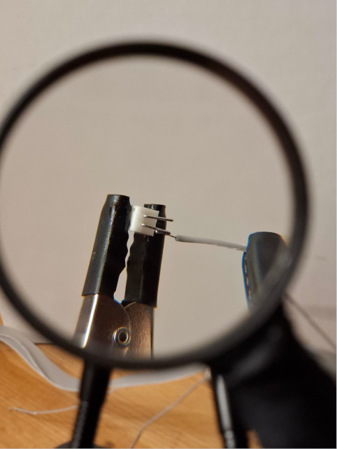
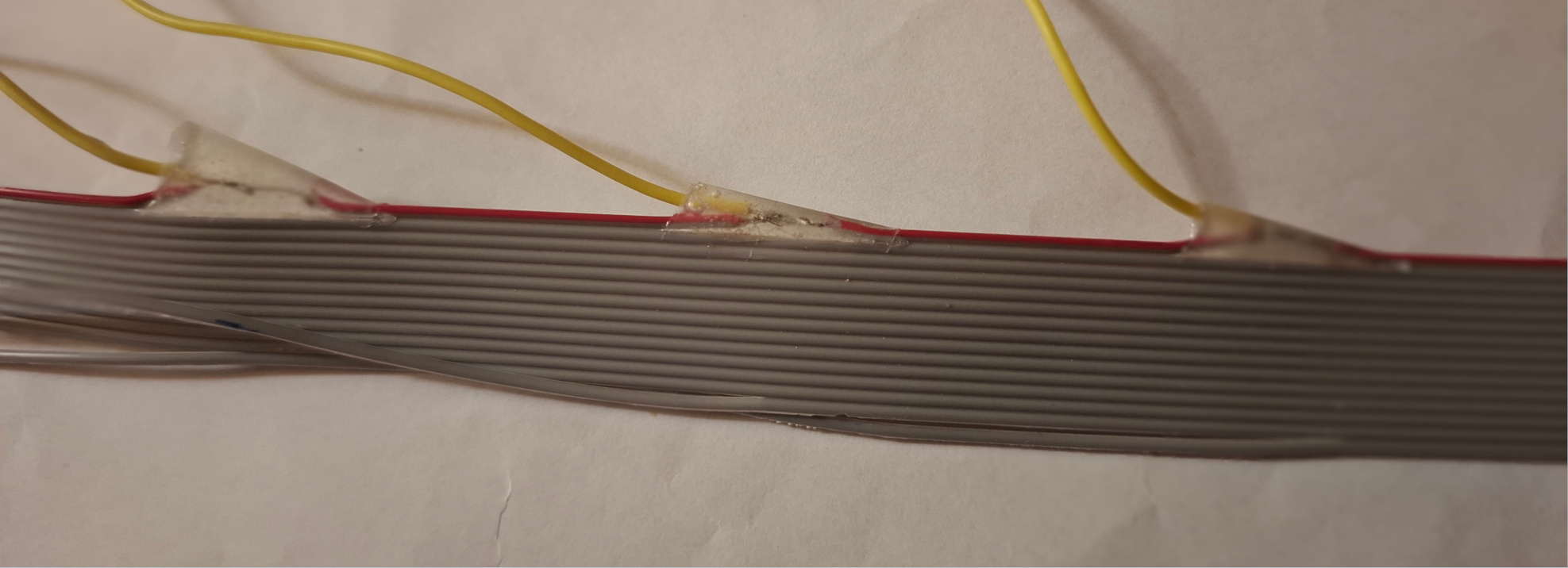
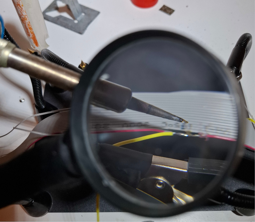
the yellow wire is attached to the second goose neck clamp from below. The soldering iron rests on the second goose neck. Be sure to smear the soldering point with soldering fluid. I try to be sparing with the tin, as tinned wire is fragile, so it's best to have as short a length as possible tinned. Soldering with magnetic flexible goose collar clips speeds up the job, as you will be needing more than two hands.
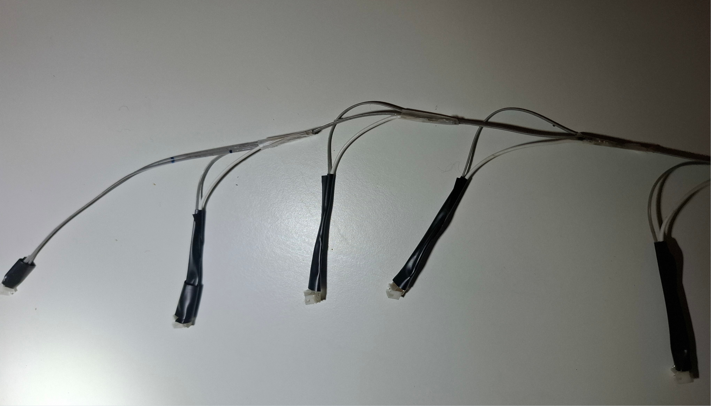
The picture shows how I wrapped electrical tape around the outlet wires to the vibration motors to keep them neatly together. There may also be a shrink tube at this point.
It is important to place the shrink tube BEFORE soldering the connector. Then I solder all connectors, and then I put a epoxi glue on all the solder points, and then I pull the shrink tube over the connector, when the epoxi is still wet.

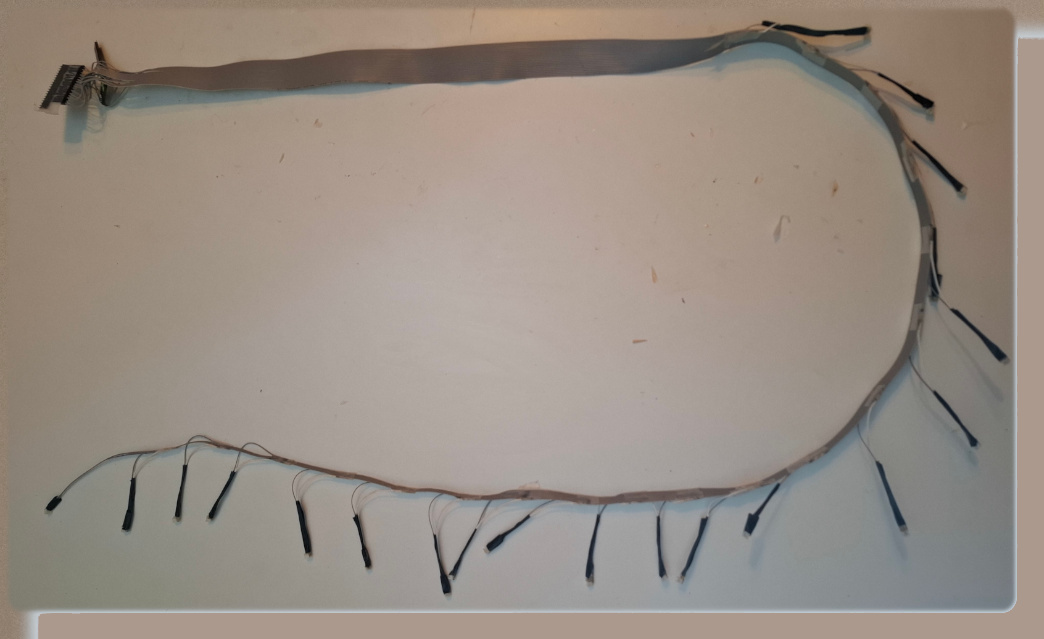
The picture shows the entire flatcable. At this stage, it is important to test everything to make sure that all solder points are conducting electricity. I think this is a much neater solution than the previous one with separate wires, resembling spaghetti.
Arrangement of the ends of the flat cable using a comb. It is better to put each wire in its own prong within the comb. It is important to get the wires in the correct order onto the terminals. When you are connecting a Dupont connector to one single wire end, the other wire ends tend to get mixed up all the time. This can be avoided by using a comb as shown in the picture. By gluing the wires with blue tape to the comb pins temporarily, the wire order will not get confused. The blue tape is also important, it can be used to hold the components in place upside down during soldering, and the blue tape can be used as a cable tie, because regular cable ties are far too big for this small case.
This shows the belt with cylindrical vibration motors. It now has yellow netting for protection, but this protection is not yet complete in this picture. The yellow mesh tape is now only attached with round pieces of Velcro. The back of the tape is adhesive and sticks to the fabric quite easily. As I write this, I think it would be best to still buy some silky fabric from a fabric store to protect all sides of the belt.
I bought a set of vibration motors for electric toothbrush use (7x25mm) with JST ZH plugs already fitted. I sewed a grey coloured tube from stretchy textile tape. The diameter of the textile tube is approximately 8 mm and its length is approximately 50 mm. I then insert the vibration motor into the textile tube and sew it onto the belt. Unfortunately, there is no proper photograph of this stage of the work. But the idea is that the vibration motor does not have any eyelets for attaching it to the belt, but this can be done with the help of the textile tube. Again, on this belt, I determined the positions on the waist accurately, but this one has such a long buckle that I had to fiddle a bit with the waistline. When I sewed these tubes on, I first made a knot at one end of the sewing thread, but as this is quite time consuming, I switched to just making a few stitches and then trusting that the thread would hold anyway and just made a few knots at the end of the stitches, so I felt that was enough. I didn't stitch the ends of the tubing closed as the motors sit in that tubing pretty tightly. I sewed these gray pieces of tubing to the ends of the yellow belt. Then I inserted the vibration motors into those grey tubes, connected the motors with plugs to the ribbon cable and tested. Unlike the button motor belt, this one had no problems at all with broken connections, the testing showed that all the motors worked flawlessly. What I learned from this is that in practice the JST-ZH connector fits much better solderably than the JST-SH due to its larger size. Will never use the JST-SH again.
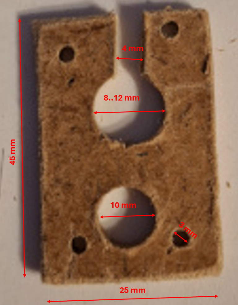
I got 3mm thick chipboard from a local wood shop. The thickness of the board must be 3mm, because that is the thickness of the vibration motor. The appropriate height is 45mm, because the width of the flexible textile band is 50mm, and I think the vibration motor housing should be a bit narrower. I drill 4 small holes with a diameter of 3mm, which I then use to sew this holder to the stretchy textile tape. For the motor I drill one 10mm hole, it will then fit tightly in the hole. You can drill several plates at the same time, and then under the plate stack there are 2 extra plates. When you do it this way, no chips come off the bottom plate and all the chamfers in the drill holes are clean and smooth. For JST-SH Plugs, 8mm drilling is sufficient. The vibration motor has a small outlet tongue, and for this tonge, I have to file a small recess with dimension of about 2mm x 2mm x 1mm, otherwise the motor does not fit snugly.
I do not have a specialized crimping tool for JST-SH plugs. Therefore I took advice from an youtuber, which only soldered without a crimper. This picture shows how I clamped down the plug with scotch tape. With this small plug, it was very important to use only a very tiny amount of tin onto the soldering iron. If too much tin, it will also fill the metal plug with tin, and then it doesn't work. I press the metal part together with small pliers, so it fits exactly into the small slit of te plug. After the work, it must be tested. I also put a small drop of epoxy glue, where the electrical cable comes out of the plug.
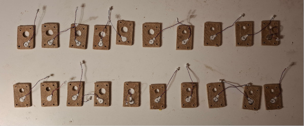
This picture shows all 20 motor holder in one picture.
There are no holes in the vibration motor to sew it to somewhere, and the motor is better suited to being attached to a cell phone casing. That's why I thought it better to make such a fixture. The upper slot between the top edge and the top hole became necessary, because the end of the shrink sleeve would not otherwise have gone into the holder.
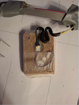
This picture shows how the transparent shrink sleeve is molded around the housing of the vibration motor to protect it tightly on all sides. I heated the heat shrink tube with a candle, and I was a little worried that the motor wouldn't survive the heat, but it stood up well to the heat of the candle, at least for a short time. I put some ordinary tape around the motor just to avoid the cable from the motor bending at too sharp an angle. In this picture you can see how the black shrink sleeve of the inlet cable is folded into an "accordion" shape so that it can take small stretching.
Before sewing the vibration motors onto the stretchy fabric belt, I marked the point on the stretchy textile belt (B=80mm) with a needle and tape where the vibration motor belongs. Of course, a tailor's chalk would be better here, but I didn't have one. Because in the sewing phase I have to constantly reposition the belt when I sew with needle and thread. The ribbon cable itself is 160mm longer than the belt itself, so that even a stouter orienteer can put it on.
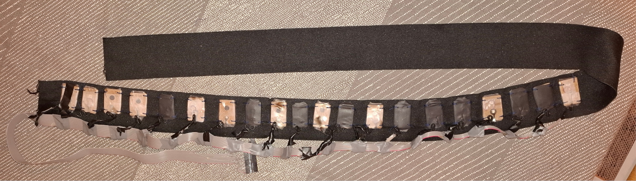
In this photo, all the vibration motors are sewn into a stretchy textile tape. The flat cable is longer and when pulled this flat cable allows for a maximum waist circumference of 110cm. But the shrink tubes don't stretch properly as much as I would have expected, they are quite stiff. They sort of rotate upwards when stretched as if they're articulated around that motor housing, and that's not quite appropriate.
I sewed the whole length of the bottom seam of the elastic textile belt closed. Then I stitched the upper part only in a few places with thread, also I found round Velcro fasteners, which I glued to the elastic textile belt.I can then more easily open this elastic belt in case of cable damage. I sewed the ends of the belt closed, and left small holes in the top and bottom so that the ends make a loop and the ribbon cable now comes out the bottom hole. I happened to have some 4mm aluminium wire coated with black plastic at home, maybe 30cm long. I bent the aluminium wire into a paper clip shape and braided it into the belt loops to form a buckle.