Yamaha e-bike motor repair
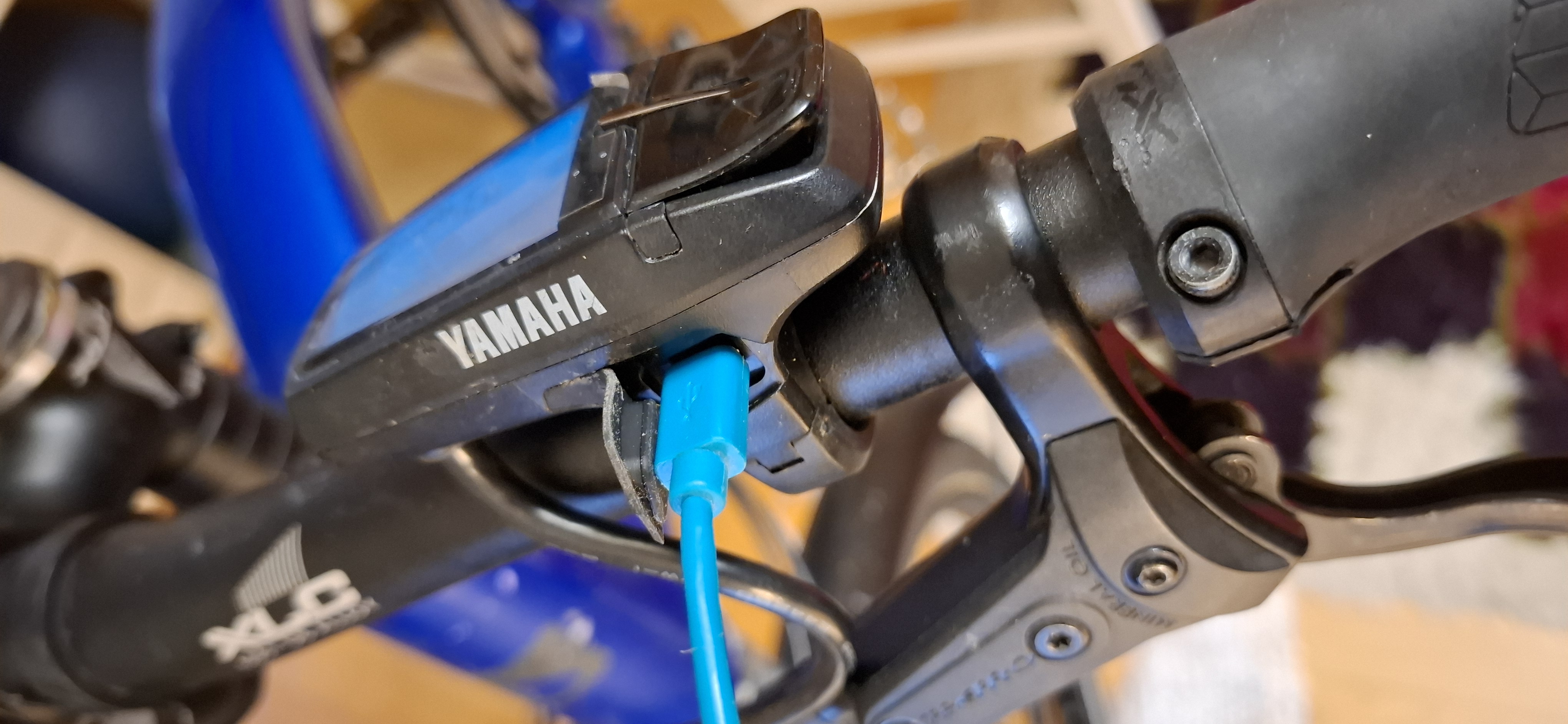
The bicycle was successfully analyzed by connecting the e-bike's control unit to a computer via a USB cable. The port on the bike is concealed beneath a small rubber cover and uses the older micro-USB standard.
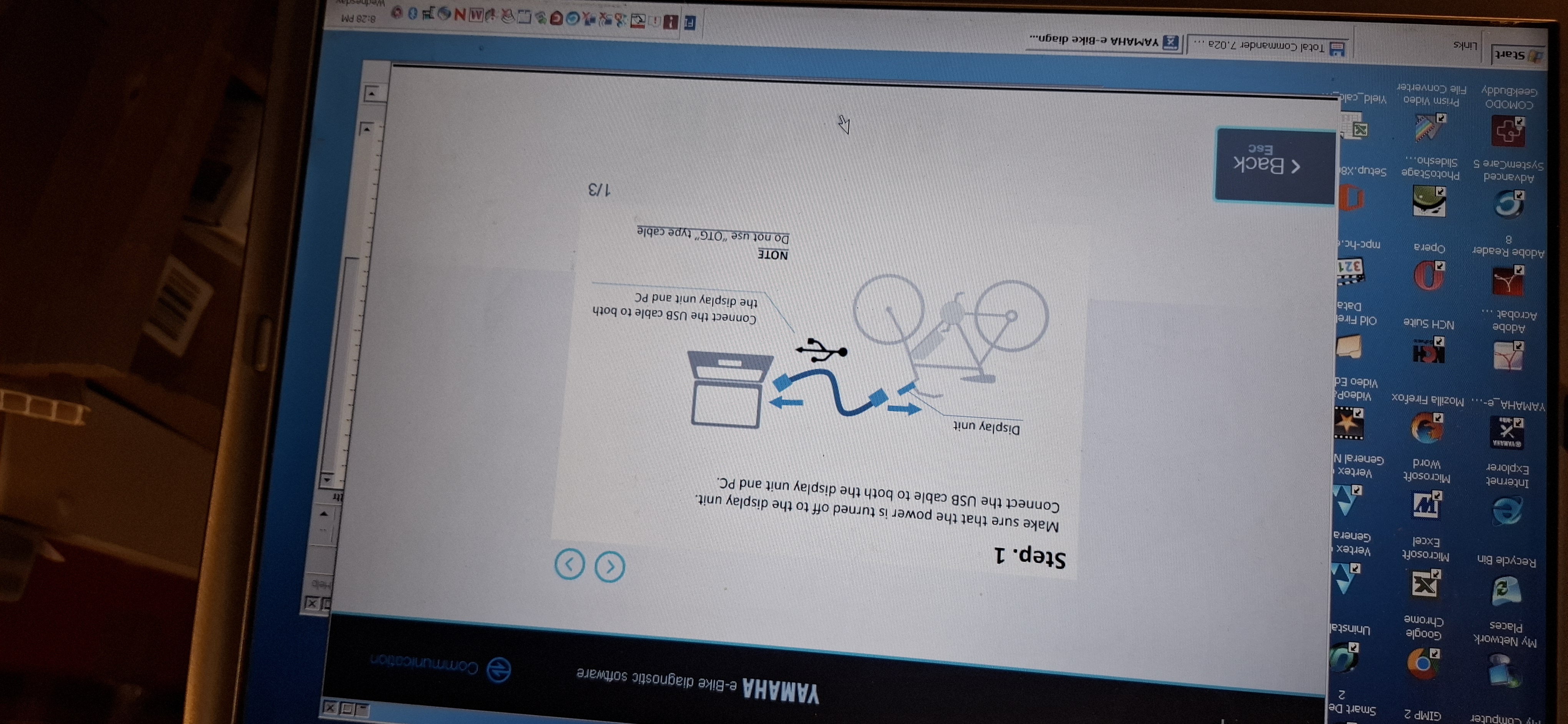
You need to install the Yamaha E-Bike Diagnostic Tool software and a virtual COM port driver on the computer. I am using an old computer that still runs Windows 98, as I didn't have the Yamaha diagnostic software for a modern operating system. With the USB connected and the program running, the software detects the control unit and retrieves data from it—specifically, error codes. It displays the error codes along with their explanations and allows you to clear old codes. It also shows the status of the motor and battery, among other details.
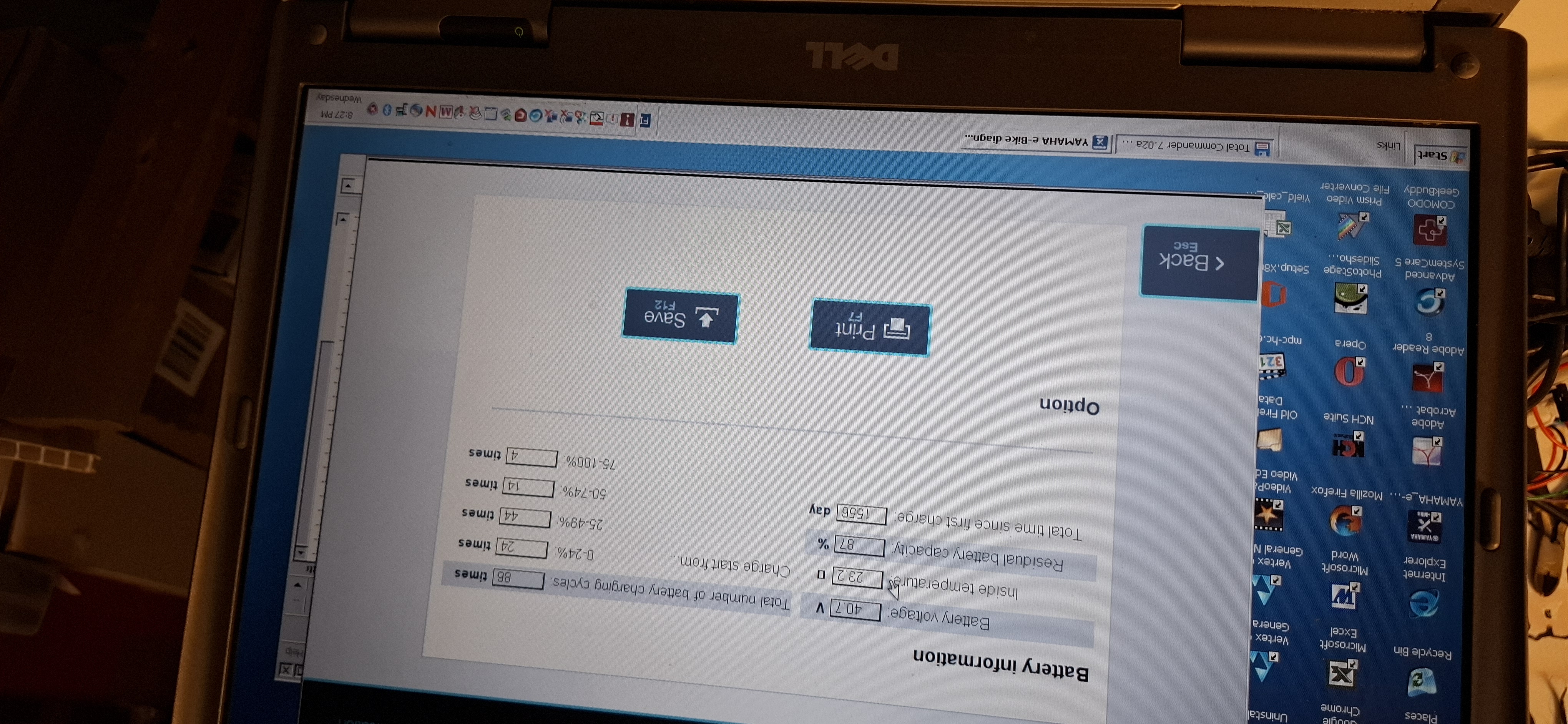
The program also displays the battery voltage, total number of charge cycles, temperature, remaining battery capacity, total time since the first charge, and the battery charge level at the time the charging cable was connected.
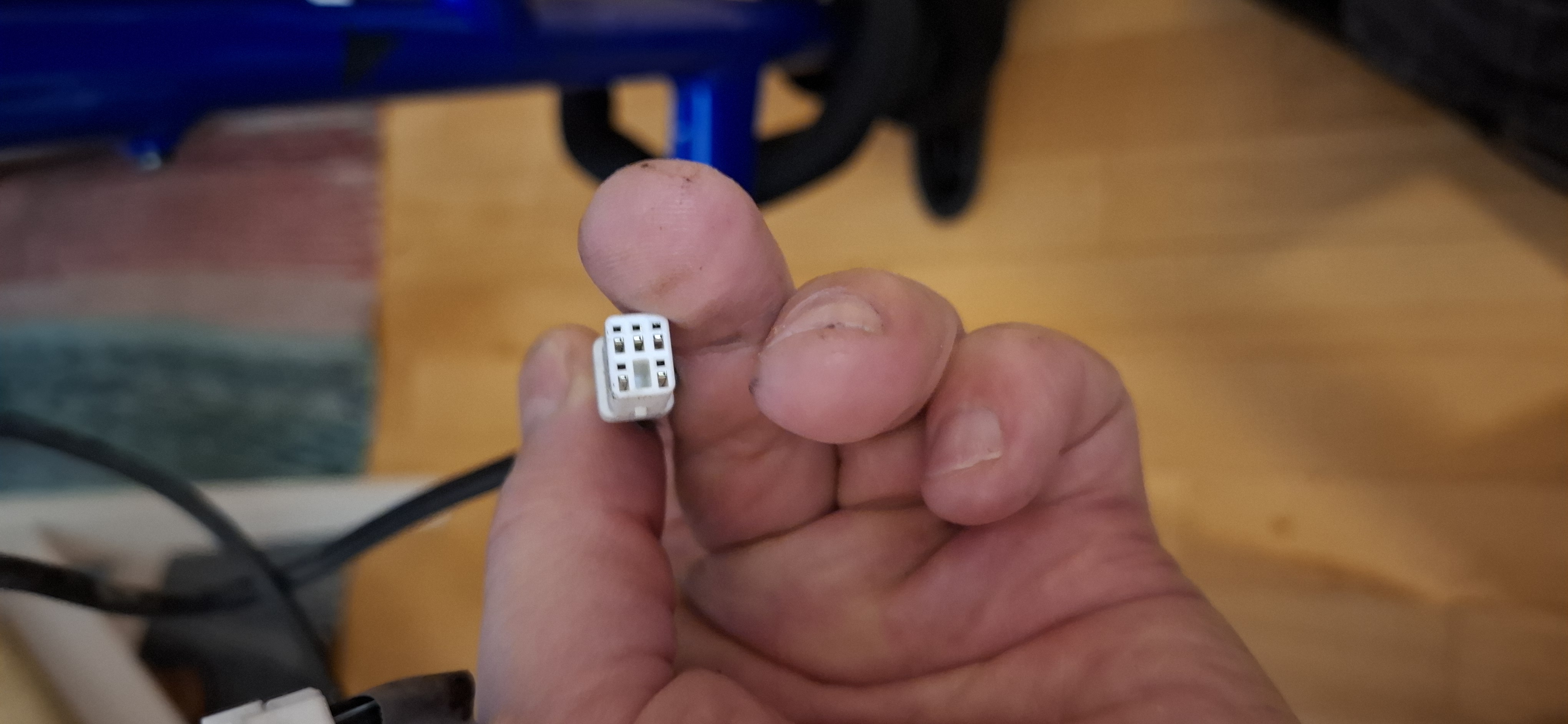
This photo shows a front view of the internal cable connector. This connector attaches to the motor and links the motor's control unit with the battery's control unit. There are 5 pins inside the connector. Data travels between the motor control unit and the handlebar controller through this connector.
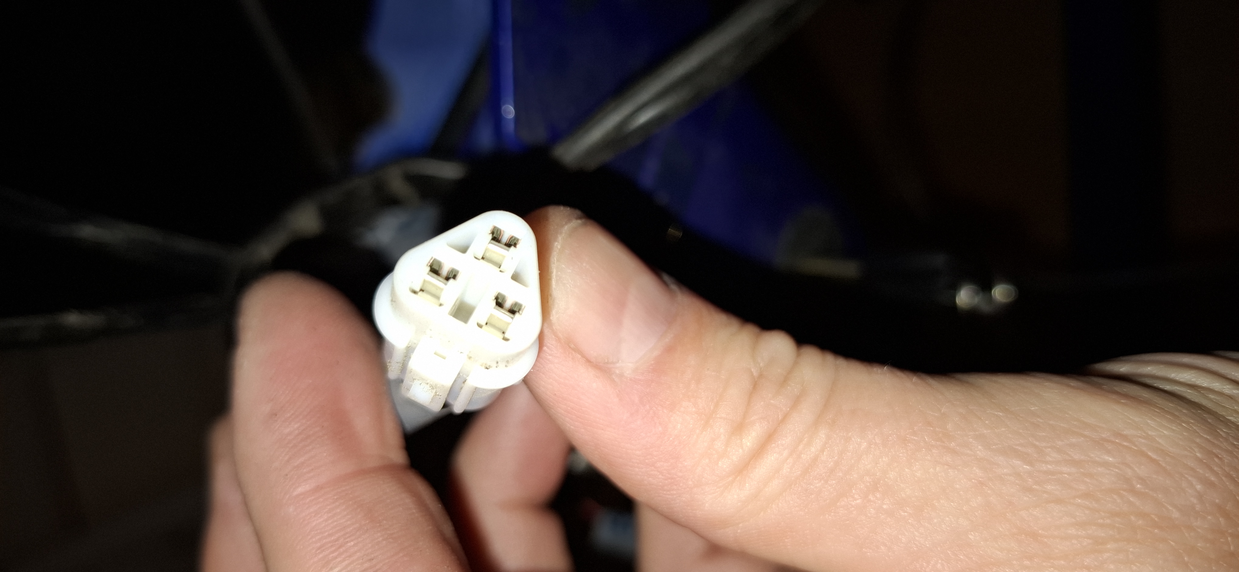
This photo shows a front view of the connector for the cable running between the motor and the battery. This connector is attached to the motor and links the motor to the battery. It has 3 pins.
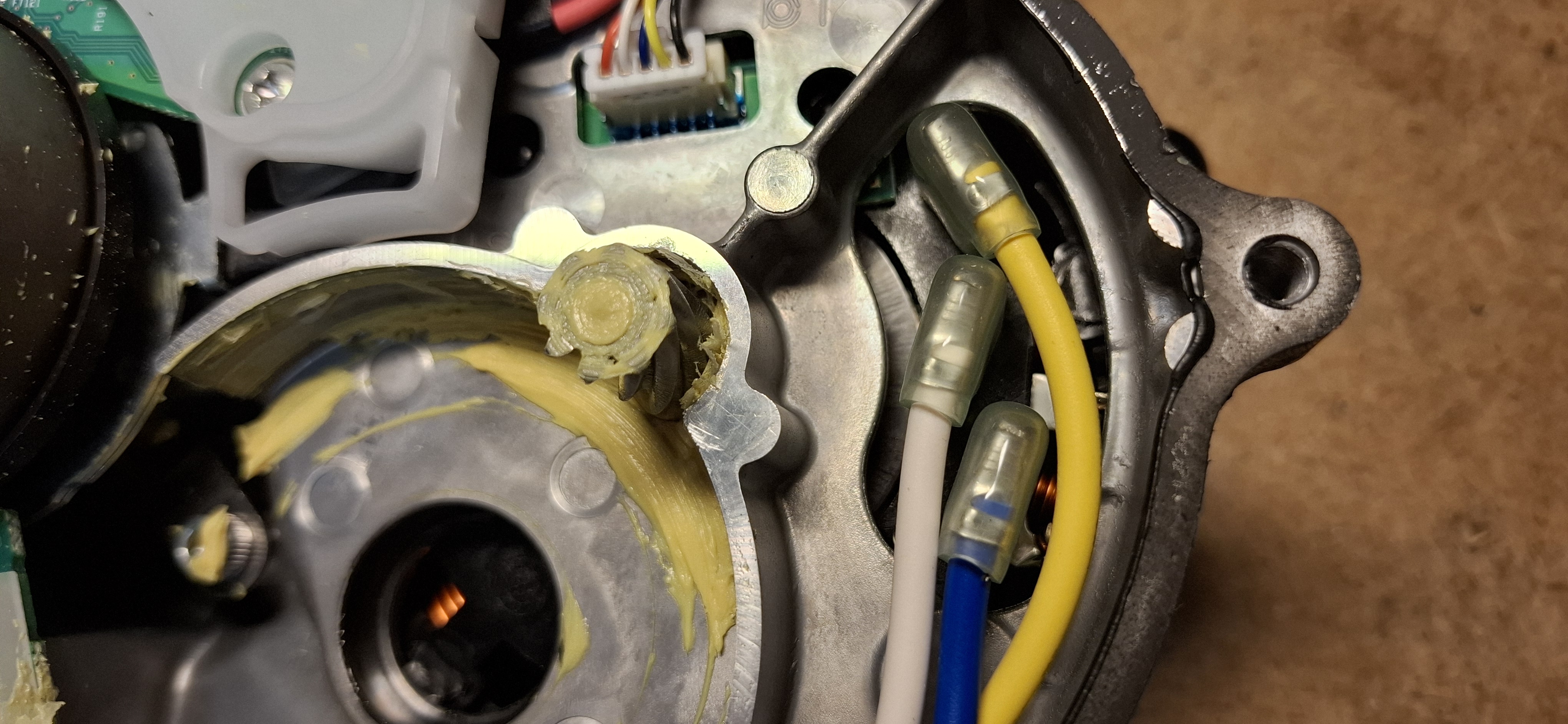
This photo shows the plugs for the blue, white, and yellow power cables inside the motor.
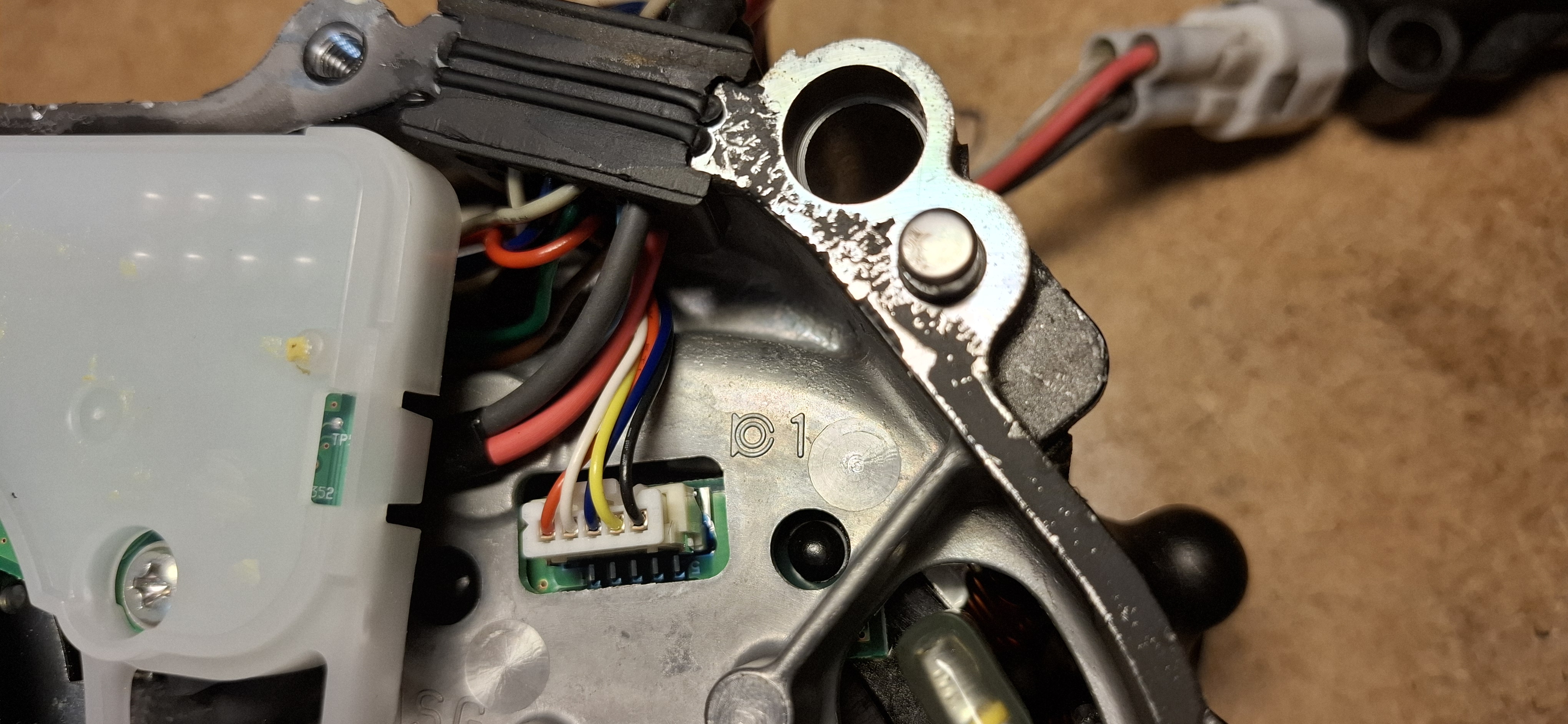
This photo shows a plug located inside the motor. The wire colors are black, yellow, dark blue, white, and red. This plug connects the motor control unit and the handlebar controller.
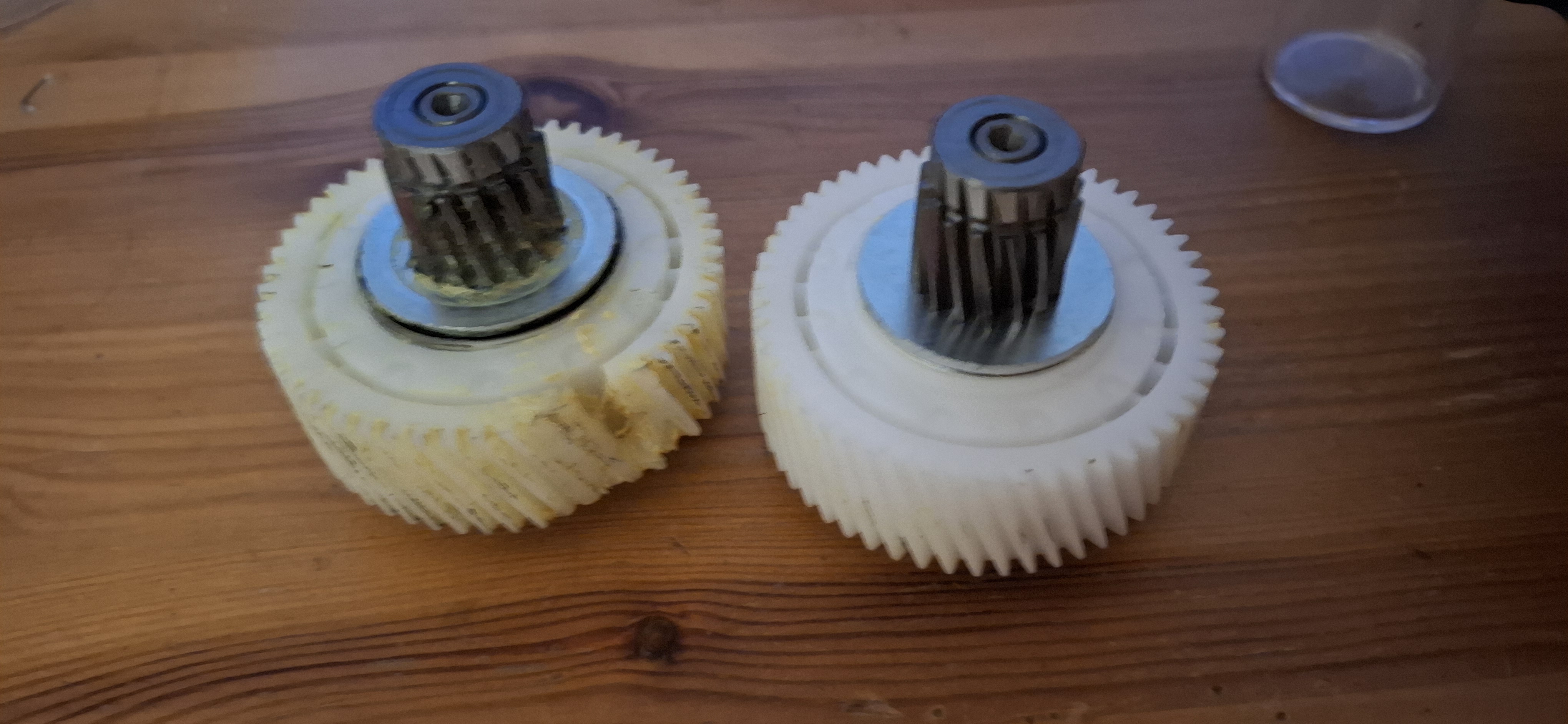
On the left is the old, worn intermediate gear, and on the right is the new one. There is a freewheel mechanism inside the gear. I assume its purpose is to allow pedaling even when the electric motor is switched off.
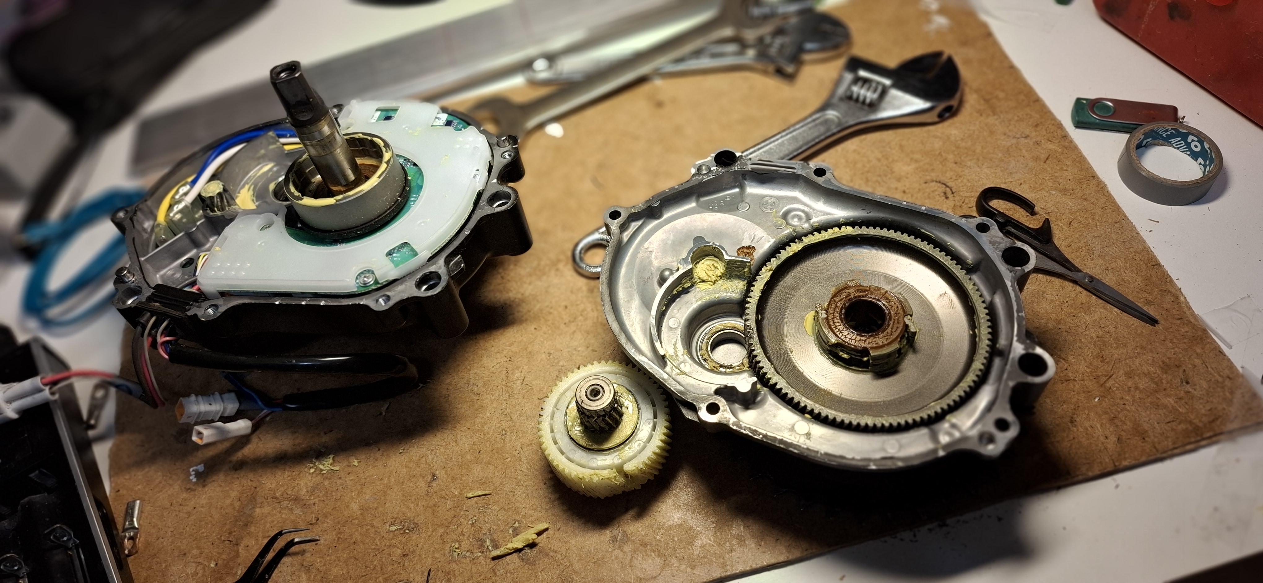
Both sides of the electric motor opened up. The motor control unit is visible on the left, while the cover containing the inner part of the ratchet clutch is on the right. The outer part of the ratchet clutch is visible on the left side. After removing all the screws from the cover, I opened the motor at the mating surface using a knife and by carefully tapping with a hammer from all sides. At first, it feels as if nothing would happen, but once a tiny gap of a millimeter opened up and the sealant gave way, it came apart very easily. Immediately after opening it, I cleaned out all the plastic chips from the interior that had broken off the intermediate gear.
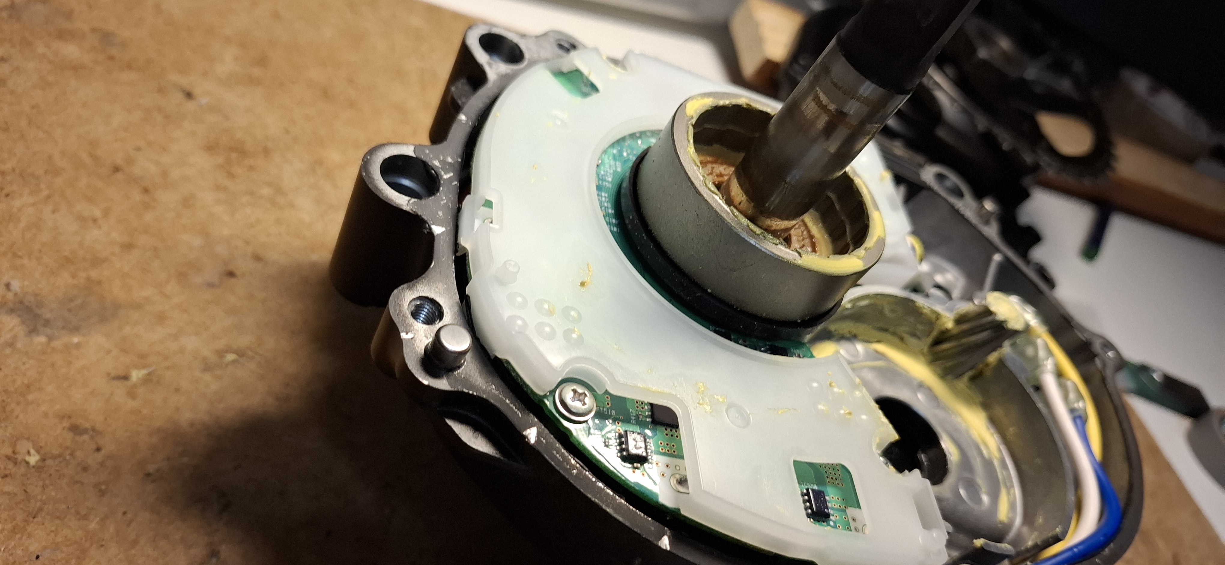
The motor control unit side, viewed from a slightly different angle
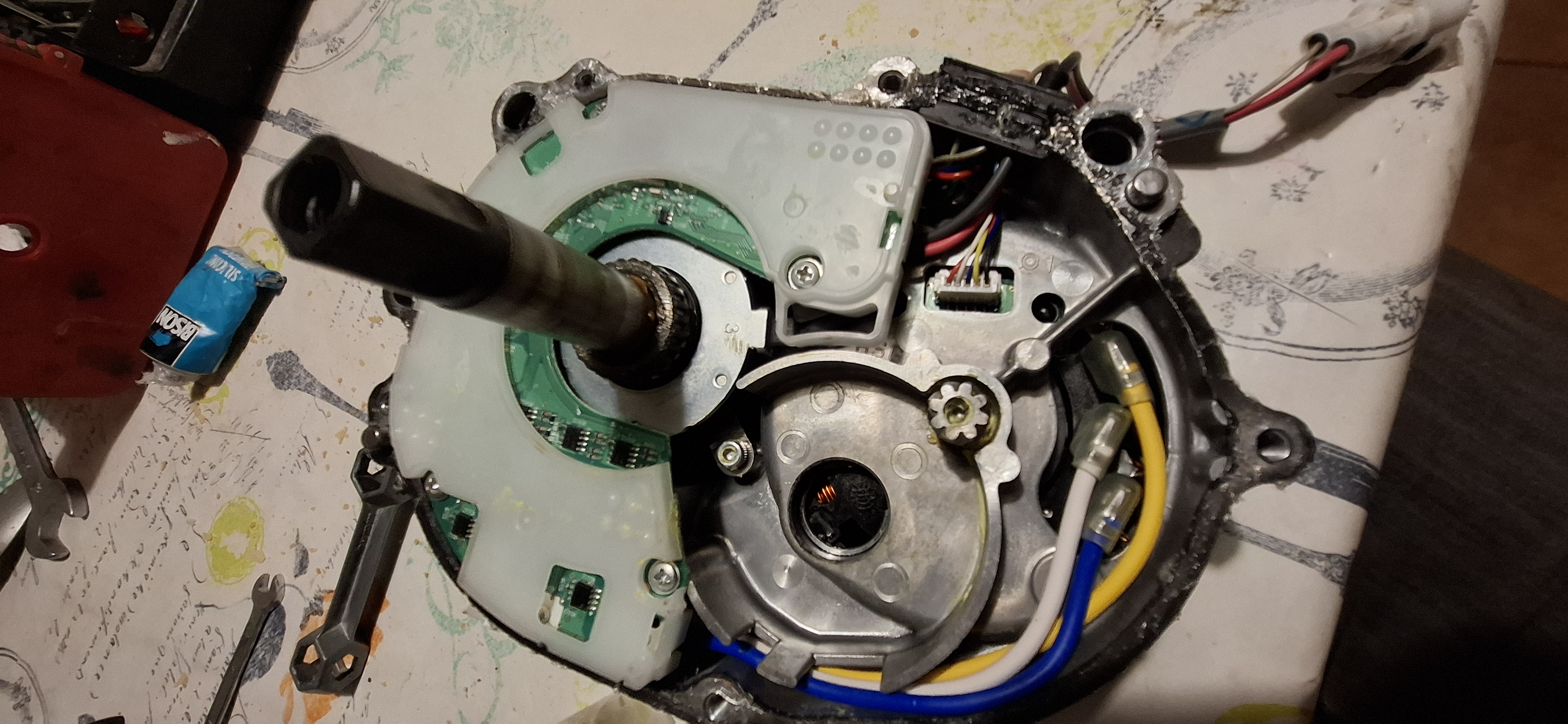
The motor control unit side, viewed from above. At the top, behind the PCB, the torque sensor is visible—the round metal part stamped with the number 3. The green PCB has a clear laquer coating.
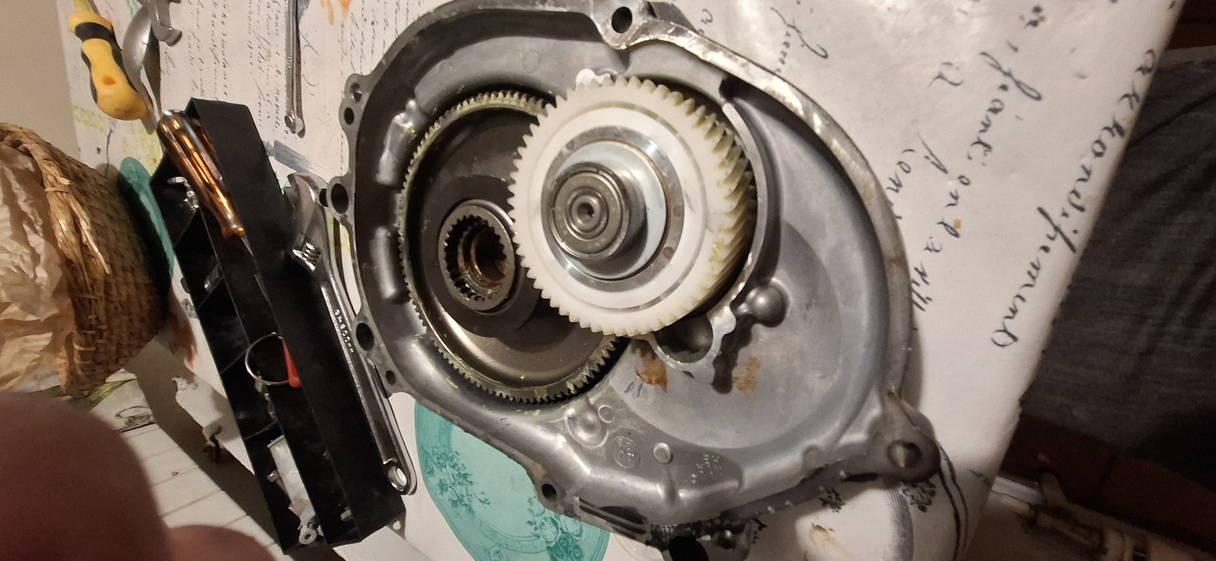
A close-up of the electric motor cover with the new intermediate gear assembly
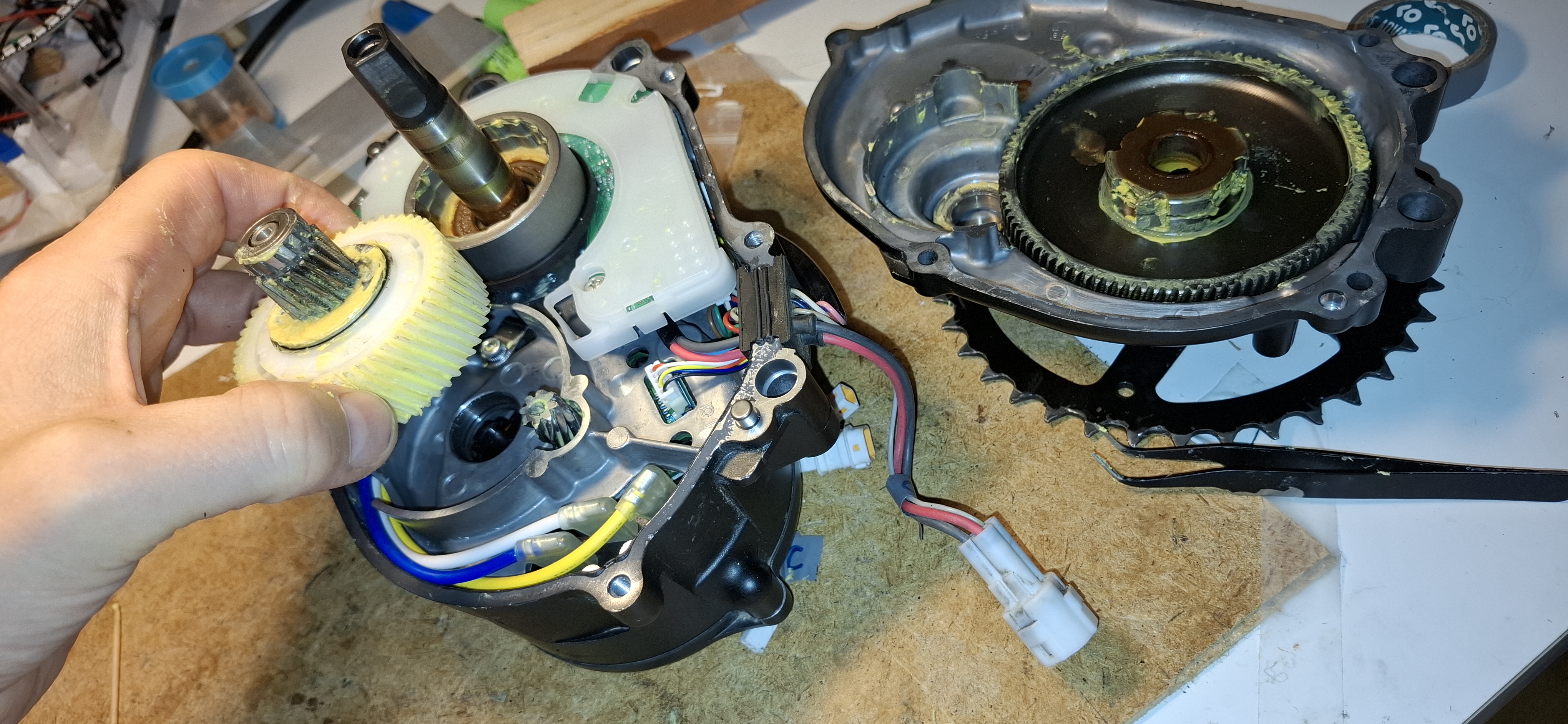
The motor control unit side, with the intermediate gear assembly held in place by hand in the position it occupies inside the motor.
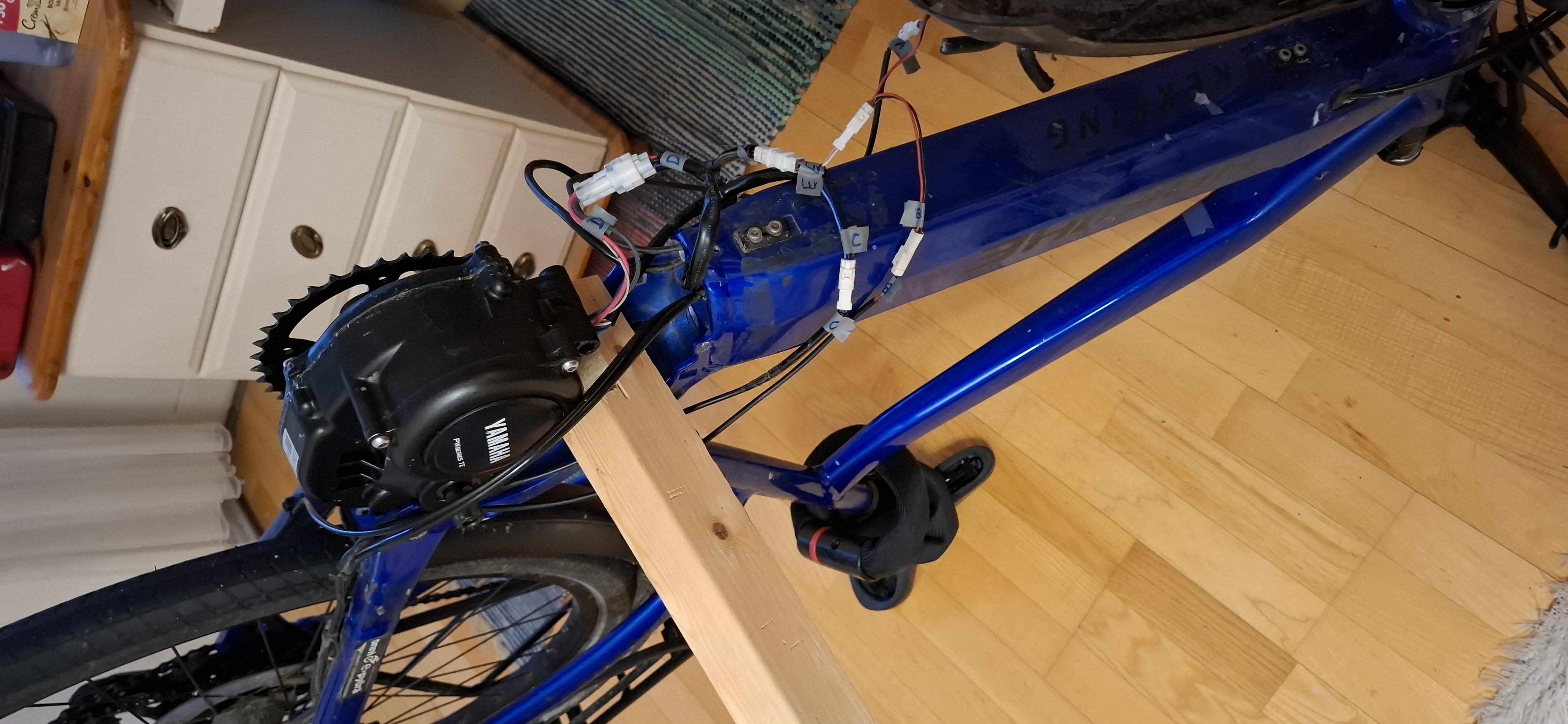
I attached the electric motor cover, having first applied silicone sealant to the mating surface. The mating surface is flat and features six screws that must be tightened evenly. The screws require a torque of 5 Nm. Next, I attached the motor control unit and tightened its screws to 5 Nm as well. Then I put the motor back onto the bike—securing it with just one screw for the moment—so I could connect the plugs. Before disassembly, I had marked both ends of the connectors with tape to avoid mixing them up, It is probably impossible to put them in the wrong way around anyway. At this stage, the hardest part was stuffing all the cables and the plug under the cover.
 cloudy